Metal structural part machining device and machining method thereof

A technology for metal structural parts and processing devices, which is applied in the field of metal structural parts processing devices, can solve the problems that the free microbead friction-assisted electroforming technology cannot meet the manufacturing requirements and other problems, and achieve the effect of smooth appearance and surface.

Active Publication Date: 2021-07-13
SHANDONG UNIV OF TECH
View PDF10 Cites 1 Cited by
  • Summary
  • Abstract
  • Description
  • Claims
  • Application Information

AI Technical Summary

Problems solved by technology

[0003] However, as the demand and manufacturing requirements for large-wall metal structural parts are getting higher and higher, for example, the thickness of the outer wall of the thrust chamber of a liquid rocket engine usually needs to reach 6-8 mm, sometimes even thicker. Free microbead friction-assisted electroforming technology unable to meet its manufacturing needs

Method used


Image

  • Metal structural part machining device and machining method thereof
  • Metal structural part machining device and machining method thereof
  • Metal structural part machining device and machining method thereof

Examples


Embodiment 1

[0045] Aiming at the problem that the frictional strength of microbeads cannot be controlled when the free microbead friction-assisted electroforming technology is used to process metal structural parts with large wall thickness, this embodiment provides a method for adjusting the friction-assisted electroforming of microbeads in the large thickness electroforming layer. Friction-strength metal structure processing device.

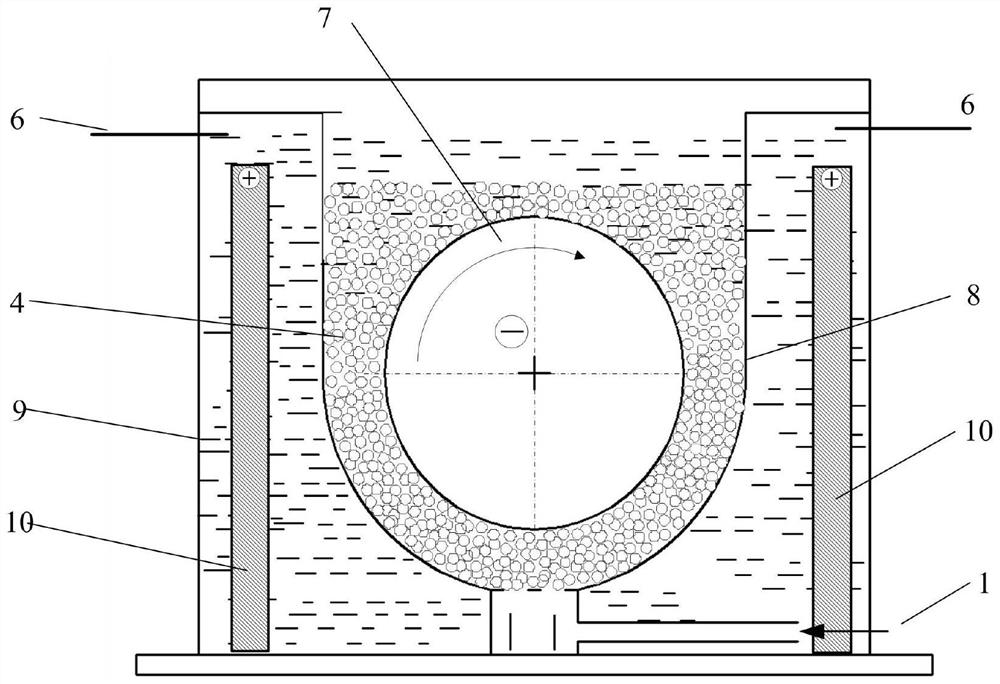
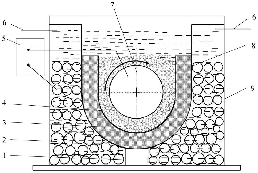
[0046] like image 3 and Figure 7 As shown, the metal structure processing device in this embodiment includes an electroforming working tank 9, an anode unit 12 located inside the electroforming working tank 9, and a porous elastic material for accommodating the metal structure (hereinafter referred to as the cathode core mold 7). Support structure 3; wherein, the inner wall surface of the porous elastic support structure 3 is an elastic surface, and the inner wall surface, the outer wall surface and the area between the inner wall surface and the outer ...

Embodiment 2

[0065] like Figure 8 As shown, the present invention also provides a processing method using the metal structure processing device described in Embodiment 1, including:

[0066] Step S1: After the metal structure is placed in the porous elastic support structure, put microbeads between the porous elastic support structure and the metal structure.

[0067] The particle size of the microbeads in this step is 0.5-1.2 mm, which is hard and has good wear resistance.

[0068] Preferably, microbeads are evenly added between the porous elastic support structure and the metal structure to form a thin layer.

[0069] Step S2: After the microbeads cover the metal structure, inject an electroforming liquid into the electroforming working tank.

[0070] Step S3: After the metal structure is submerged in the electroforming solution, electroforming is performed on the metal structure.

[0071] During the electroforming process, the micro-grinding of the electroformed layer is achieved by...


PUM

PropertyMeasurementUnit
densityaaaaaaaaaa
hardnessaaaaaaaaaa

Abstract

The invention discloses a metal structural part machining device and a machining method thereof and relates to the technical field of electroforming machining. The device comprises an electroforming working tank, an anode unit located in the electroforming working tank, and a porous elastic supporting structural part for containing a metal structural part, wherein the inner wall surface of the porous elastic supporting structural part is an elastic surface; in a working state, micro-beads are arranged between the elastic surface and the metal structural part; and the microbeads cover the metal structural part. When the distance between the surface of the metal structural part and the anode unit is gradually reduced, a large number of hard microbeads extrude the porous elastic supporting structural part, the pressure of the hard microbeads and the surface of a cathode core mold is released on the porous elastic supporting structural part, and the requirement for manufacturing the large-wall-thickness metal structural part with the larger thickness is met.

Description

technical field [0001] The invention relates to the technical field of electroforming processing, in particular to a processing device and a processing method for metal structural parts. Background technique [0002] The free microbead friction-assisted electroforming technology is widely used in the field of metal structural parts manufacturing technology because it can completely remove the defects such as pinholes, pits and nodules in the electroforming layer in the traditional electroforming technology. The special processing method of formed parts has an important application in the manufacture of metal structural parts with large wall thickness. For example, it has a very important application in the manufacture of parts with large wall thickness such as the special structure of the thrust chamber of liquid hydrogen and liquid oxygen rocket engines, large supersonic wind tunnel nozzles, large pressure vessels, and large reflectors. [0003] However, with the increasin...

Claims


Application Information

Patent Timeline
Patent Type & Authority Applications(China)
IPC IPC(8): C25D5/22C25D17/12C25D21/12
CPCC25D5/22C25D17/12C25D21/12
Inventor 任建华王兆新尹冠华姚传慧
Owner SHANDONG UNIV OF TECH
Why Eureka
Try Eureka