
Wear-resistant water pump

A wear-resistant, water pump technology, applied in the direction of pumps, pump components, non-variable-capacity pumps, etc., can solve the problems of large vibration of the water pump, easy to sink to the bottom, heavy water pipe body, etc., to achieve the effect of easy recovery of the device and easy replacement.

Pending Publication Date: 2021-07-13
徐翠华
View PDF5 Cites 0 Cited by
  • Summary
  • Abstract
  • Description
  • Claims
  • Application Information

AI Technical Summary

Problems solved by technology

[0003] When the water pump is directly placed on the bottom of the water, due to the heavy water pipe and its body, it is easy to sink to the bottom, not only inconvenient to move, but also easy to sink into the bottom mud. During the process of pumping liquid, the pressure of the instantaneous injection at the water outlet is high, resulting in relatively high vibration of the pump. Large, reducing the stability of the pump

Method used


Image

  • Wear-resistant water pump
  • Wear-resistant water pump
  • Wear-resistant water pump

Examples


Embodiment 1

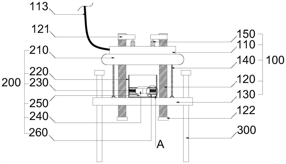
[0039] see figure 1 , the present invention provides a technical solution: a wear-resistant water pump includes a fixing mechanism 100 and a moving mechanism 200 , wherein the moving mechanism 200 is fixed on one side of the fixing mechanism 100 .

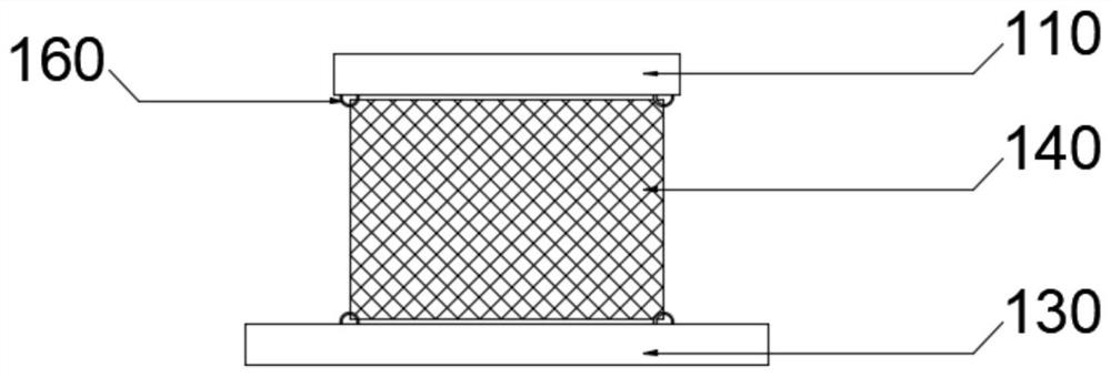
[0040] see figure 1 , 2, 3 and 5, the fixed mechanism 100 includes a fixed plate 110, a threaded rod 120, a base 130, a mesh cover 140 and a motor 150, the middle of the fixed plate 110 is provided with a first through hole 111, and one side of the fixed plate 110 is provided with a cable 113, and the screw thread There are two rods 120, one end of the two threaded rods 120 rotates through the inside of the fixed plate 110, the base 130 is threaded on the threaded rod 120, one end of the mesh cover 140 is fixed on one side of the fixed plate 110, and the surface of the fixed plate 110 is provided with Bearing block 112, fixed plate 110 and base 130 one side are provided with hook 160, net cover 140 two ends are hung on the hook 1...

Embodiment 2

[0043] see figure 1 , the present invention provides a technical solution: a wear-resistant water pump includes a fixing mechanism 100 and a moving mechanism 200 , wherein the moving mechanism 200 is fixed on one side of the fixing mechanism 100 .

[0044] see figure 1 , 2 , 3 and 5, the fixed mechanism 100 includes a fixed plate 110, a threaded rod 120, a base 130, a mesh cover 140 and a motor 150, the middle of the fixed plate 110 is provided with a first through hole 111, and one side of the fixed plate 110 is provided with a cable 113, and the screw thread There are two rods 120, one end of the two threaded rods 120 rotates through the inside of the fixed plate 110, the base 130 is threaded on the threaded rod 120, one end of the mesh cover 140 is fixed on one side of the fixed plate 110, and the surface of the fixed plate 110 is provided with Bearing block 112, fixed plate 110 and base 130 one side are provided with hook 160, net cover 140 two ends are hung on the hook ...


PUM


Abstract

The invention provides a wear-resistant water pump, and belongs to the technical field of water pumps. The wear-resistant water pump comprises a fixing mechanism and a moving mechanism, the fixing mechanism comprises a fixing plate, two threaded rods, a base, a mesh enclosure and a motor, a first through hole is formed in the middle of the fixing plate, the moving mechanism comprises an air cushion, a sleeve, a spring, a clamping block, a water pump body and a sliding rail, the air cushion is fixed to one side of the fixing plate, a plurality of second through holes are formed in the surface of the sleeve, one end of the sleeve is fixed to the surface of the base, the clamping block is fixed to the other end of the spring, and the clamping block abuts against the surface of the water pump body. When the wear-resistant water pump is put into water, the distance between the water pump and the water bottom can be adjusted, the water pump cannot be sunk into sludge, the air cushion at one end facilitates movement of the water pump, the spring and the clamping block more effectively buffer and support the water pump body, and the stability of the water pump body is improved.

Description

technical field [0001] The invention relates to the field of water pumps, in particular to a wear-resistant water pump. Background technique [0002] A pump is a machine that transports or pressurizes a liquid. It transmits the mechanical energy of the prime mover or other external energy to the liquid to increase the energy of the liquid. It is mainly used to transport liquids including water, oil, acid and alkali, emulsion, suspoemulsion and liquid metal. Liquids, gas mixtures and liquids containing suspended solids can also be transported. [0003] When the water pump is directly placed on the bottom of the water, due to the heavy water pipe and its body, it is easy to sink to the bottom, not only inconvenient to move, but also easy to sink into the bottom mud. During the process of pumping liquid, the pressure of the instantaneous injection at the water outlet is high, resulting in relatively high vibration of the pump. Large, reducing the stability of the pump. Cont...

Claims


Application Information

Patent Timeline
Patent Type & Authority Applications(China)
IPC IPC(8): F04D29/00F04D29/70F04D29/66
CPCF04D29/007F04D29/708F04D29/669
Inventor 徐翠华
Owner 徐翠华
Learn More