Method for realizing ZPW-2000 track circuit calibration intelligentization
A ZPW-2000, track circuit technology, applied in the direction of circuit devices, electrical components, control/regulation systems, etc., can solve the problems of increasing the workload of personnel, affecting the progress of the project, and prone to errors, so as to reduce the probability of manual errors and realize Intelligence and automation, the effect of ensuring authenticity and reliability
- Summary
- Abstract
- Description
- Claims
- Application Information
AI Technical Summary
Problems solved by technology
Method used
Image
Examples
Embodiment approach 1
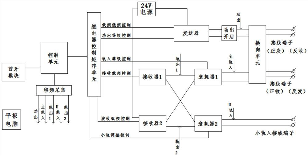
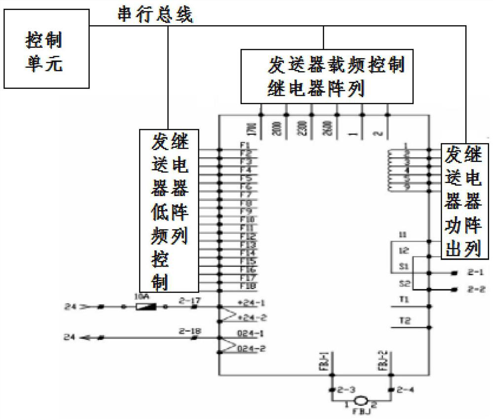
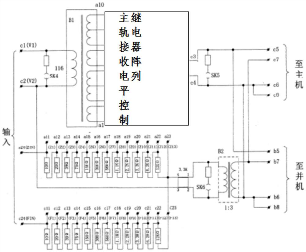
[0029] Implementation mode 1: if Figures 1 to 3As shown, the method for realizing the intelligentization of ZPW-2000 track circuit standardization is realized through an intelligent standardization system. The intelligent standardization system includes a control terminal and an execution terminal, and the control terminal is wirelessly connected to the execution terminal; the control terminal is installed There is an application software including cable length algorithm, built-in cable compensation standard, and analog network terminal connection relationship corresponding to the compensation length. The execution end includes a control unit, a Bluetooth module, a relay matrix unit, a transmitter, a commutation unit, and an attenuator . Receiver, wherein, the control unit communicates with the control terminal through the Bluetooth module, the output end of the control unit is connected to the input end of the transmitter through the relay matrix unit, and the output end of t...
Embodiment approach 2
[0030] Embodiment 2: In this method for realizing the intelligentization of ZPW-2000 track circuit standard adjustment, the input end of the control unit is connected with a frequency-shifting acquisition module, and the input end of the frequency-shifting acquisition module is respectively connected to the transmitter, attenuation device, receiver output. In this way, the host of the device is designed with built-in frequency shift acquisition simulation to realize automatic acquisition and measurement of power output voltage, power output current, main rail input voltage, rail output 1 voltage, U rail input voltage, and rail output 2 voltage, and the measurement results can be uploaded wirelessly To the software, the software displays the measurement data and judges whether the measurement data conforms to the specified range of the adjustment rules of the adjustment table. The remaining structures and components are as described in Embodiment 1 and will not be described aga...
Embodiment approach 3
[0031] Embodiment 3: The input terminal of the relay matrix unit is connected to the output terminal of the control unit in this method for realizing the intelligentization of ZPW-2000 track circuit standard adjustment, and the output terminal of the relay matrix unit is respectively connected to the transmitter, the attenuation The input terminals of the device, receiver, and frequency shift acquisition module are connected. With this design, the power output level control, carrier frequency selection, and low frequency selection terminals of the transmitter are respectively connected to the corresponding relay array module. The level is automatically controlled, and according to the carrier frequency and low frequency selection of the software, the carrier frequency and low frequency of the transmitter are automatically controlled through the relay array. The receiving level control terminal of the main rail of the attenuator is connected to the corresponding relay array mod...
PUM
 Abstract
Description
Claims
Application Information
 - R&D
- Intellectual Property
- Life Sciences
- Materials
- Tech Scout
- Unparalleled Data Quality
- Higher Quality Content
- 60% Fewer Hallucinations
Browse by: Latest US Patents, China's latest patents, Technical Efficacy Thesaurus, Application Domain, Technology Topic, Popular Technical Reports.
© 2025 PatSnap. All rights reserved.Legal|Privacy policy|Modern Slavery Act Transparency Statement|Sitemap|About US| Contact US: help@patsnap.com


