
Single-cavity resonator and radio frequency cavity filter

A resonator, resonant cavity technology, applied in waveguide-type devices, electrical components, circuits, etc., can solve the problems of limited circular resonator resonance frequency, inability to realize cavity filter, unfavorable production automation, etc., to reduce the volume and weight, the overall structure is simplified, and the molding is convenient.

Active Publication Date: 2021-07-13
LUXSHARE PRECISION INDUSTRY (CHUZHOU) CO LTD
View PDF7 Cites 4 Cited by
  • Summary
  • Abstract
  • Description
  • Claims
  • Application Information

AI Technical Summary

Problems solved by technology

However, there are many problems in the existing traditional cavity filter, which are mainly reflected in: 1. Limited by the resonance frequency of the circular resonator, it is impossible to achieve a smaller size and lighter weight design of the cavity filter; 2. , There are many types of materials in traditional cavity filters (such as adjustment screws, lock nuts and set screws, etc.), and the assembly relationship is complicated. It is necessary to manually adjust the depth of each adjustment screw inserted into the corresponding cylindrical resonator one by one. Frequency modulation of the resonant cavity is not conducive to the realization of production automation

Method used


Image

  • Single-cavity resonator and radio frequency cavity filter
  • Single-cavity resonator and radio frequency cavity filter
  • Single-cavity resonator and radio frequency cavity filter

Examples


Embodiment Construction

[0046] In order to make the technical problems solved by the present invention, the technical solutions adopted and the technical effects achieved clearer, the technical solutions of the present invention will be further described below in conjunction with the accompanying drawings and through specific implementation methods.

[0047] In the description of the present invention, unless otherwise clearly specified and limited, the terms "connected", "connected" and "fixed" should be understood in a broad sense, for example, it can be a fixed connection, a detachable connection, or an integrated ; It can be a mechanical connection or an electrical connection; it can be a direct connection or an indirect connection through an intermediary, and it can be the internal communication of two components or the interaction relationship between two components. Those of ordinary skill in the art can understand the specific meanings of the above terms in the present invention in specific si...


PUM


Abstract

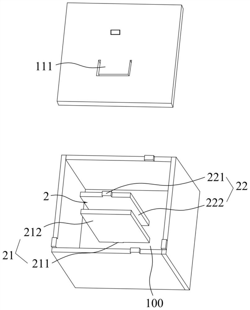
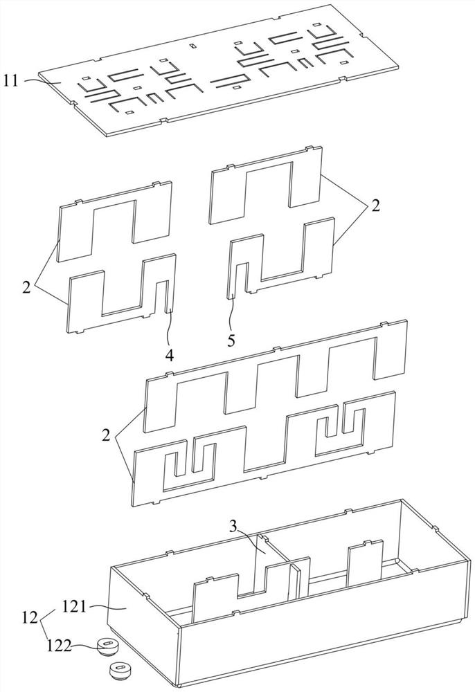
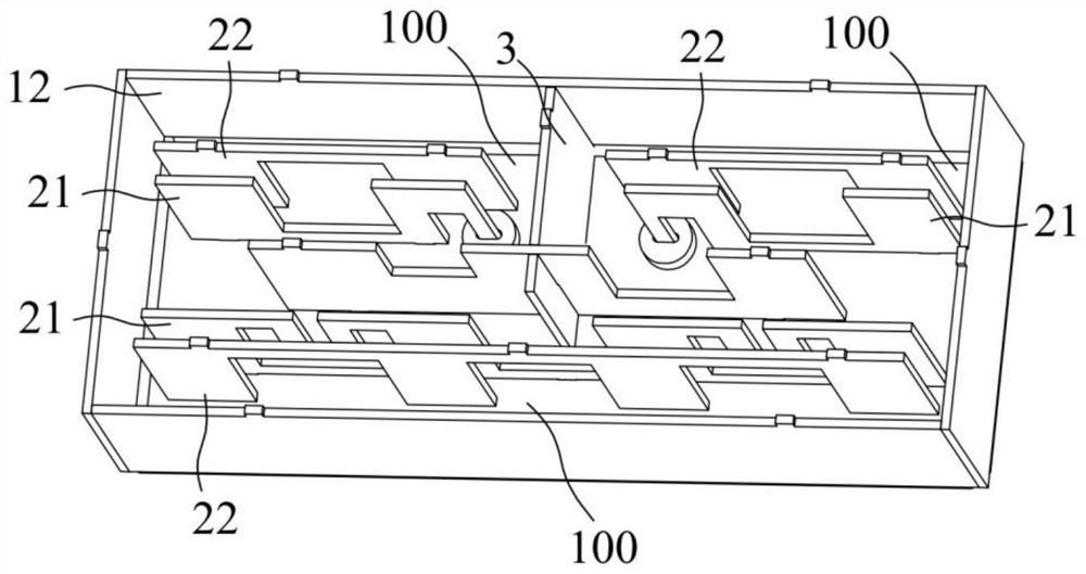
The invention relates to the field of communication devices, and discloses a single-cavity resonator and a radio frequency cavity filter. The single-cavity resonator comprises a shell which is internally provided with a resonant cavity; a cover body which covers the shell, wherein the resonant cavity is located in the shell and the cover body; a resonant piece which comprises a sheet-shaped first resonant piece and a sheet-shaped second resonant piece, wherein the first resonant piece comprises a first connecting end and a first resonant end which are integrated, the first connecting end is connected with the resonant cavity, and the first resonant end is located in the resonant cavity and is separated from the inner wall of the resonant cavity; the second resonant piece comprises a second connecting end and a second resonant end which are integrated, the second connecting end is connected with the resonant cavity, the second resonant end is located in the resonant cavity and is spaced from the inner wall of the resonant cavity, the first resonance end and the second resonance end are spaced to form a frequency modulation interval. The single-cavity resonator is small in size, light in weight, simple in structure and few in parts, and is suitable for developing the radio frequency cavity filter which is small in size, light in weight, simple in structure and few in parts. The radio frequency cavity filter is small in size, light in weight, simple in structure and few in parts.

Description

technical field [0001] The invention relates to the technical field of communication equipment, in particular to a single cavity resonator and a radio frequency cavity filter. Background technique [0002] A cavity filter is a microwave filter with a resonant cavity structure. A cavity can be equivalent to an inductor connected in parallel with a capacitor to form a resonant stage to realize microwave filtering. It is an indispensable important device in the communication system, and its performance directly affects the performance index of the entire communication system. [0003] The cavity filter is mainly composed of a cavity, a cover plate covering the cavity, debugging screws, lock nuts and set screws, among which there are resonant columns on the cavity, and the cover plate is equipped with Screw vias for screws and debug screws. With the upgrading and development of communication technology, related products put forward higher requirements for the miniaturization a...

Claims


Application Information

Patent Timeline
Patent Type & Authority Applications(China)
IPC IPC(8): H01P1/207H01P1/208
CPCH01P1/207H01P1/208
Inventor 葛文王烨孙兴华
Owner LUXSHARE PRECISION INDUSTRY (CHUZHOU) CO LTD
Learn More