Hybrid magnetic flux composite structure disc type motor

A composite structure, disc motor technology, applied in the direction of magnetic circuit shape/style/structure, magnetic circuit, electric components, etc., can solve the problems of low ratio of converted energy to volume and weight, low energy conversion efficiency of disc motors, etc.

Pending Publication Date: 2021-07-13
ZHEJIANG PANGOOD POWER TECH CO LTD
View PDF0 Cites 2 Cited by
  • Summary
  • Abstract
  • Description
  • Claims
  • Application Information

AI Technical Summary

Problems solved by technology

[0002] At present, the energy conversion efficiency of disc motors is low, and the ratio of converted energy to volume and weight is relatively low

Method used


Image

  • Hybrid magnetic flux composite structure disc type motor
  • Hybrid magnetic flux composite structure disc type motor
  • Hybrid magnetic flux composite structure disc type motor

Examples


Embodiment 1

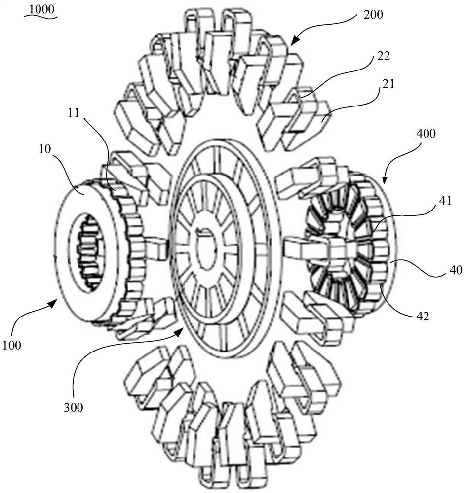
[0074] Such as figure 1 As shown, the present invention provides a hybrid flux composite structure disc motor 1000 , wherein the hybrid flux composite structure disc motor 1000 includes a front stator assembly 100 , a middle stator assembly 200 and a rotor assembly 300 .

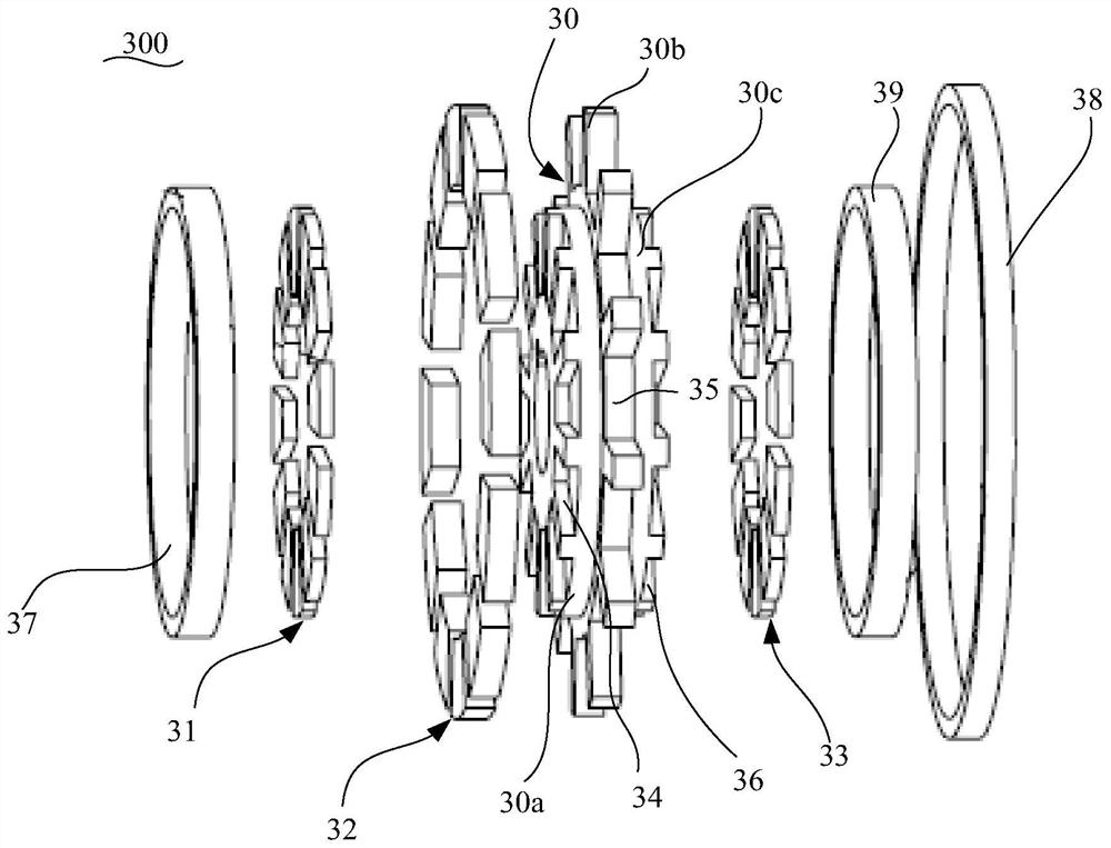
[0075] Such as figure 2 As shown, the rotor assembly 300 includes a magnetically permeable rotor bracket 30, a front end permanent magnet 31 and an intermediate permanent magnet 32, the front end permanent magnet 31 and the intermediate permanent magnet 32 ​​are installed on the magnetically permeable rotor bracket 30, and the intermediate permanent magnet 32 ​​surrounds A permanent magnet 31 is provided on the front end. Specifically, the number of the front end permanent magnets 31 and the middle permanent magnets 32 are multiple, and the front end permanent magnets 31 and the middle permanent magnets 32 are uniformly distributed on the magnetic permeable rotor support 30 along the circumferential direct...

Embodiment 2

[0081] In the second embodiment provided by the present invention, the structure of the hybrid flux composite structure disc motor 1000 in this embodiment is similar to that of the hybrid flux composite structure disc motor 1000 in the first embodiment, and the similarities are not discussed. Again, just the differences.

[0082] In this embodiment, the present invention specifically discloses that the hybrid magnetic flux composite structure disc motor 1000 also includes a rear stator assembly 400, and the rotor assembly 300 also includes a rear end permanent magnet 33, and the rear end permanent magnet 33 is installed on the magnetically permeable rotor bracket 30 and set back to back with the front permanent magnet 31, the rear stator assembly 400 and the rear permanent magnet 33 face to face, that is, the rear stator core 40 of the rear stator assembly 400 faces the rear permanent magnet 33.

[0083] Further, the present invention discloses that the magnetic permeable roto...


PUM


Abstract

The invention discloses a hybrid magnetic flux composite structure disc type motor which comprises a front stator assembly, a middle stator assembly and a rotor assembly. The rotor assembly comprises a magnetic conductive rotor support, a front end face permanent magnet and a middle permanent magnet, the front end face permanent magnet and the middle permanent magnet are both installed on the magnetic conductive rotor support, and the middle permanent magnet is arranged around the front end face permanent magnet; the front stator assembly and the front end face permanent magnet are arranged face to face; and the middle permanent magnets are arranged in the stator grooves of the middle stator assembly, and the side walls of the middle permanent magnets are away from the side walls of the stator grooves by a preset distance. According to the hybrid magnetic flux composite structure disc type motor, closed magnetic field loops are formed between the front stator assembly and the front end face permanent magnet and between the middle permanent magnet and the middle stator assembly respectively, the energy conversion efficiency is improved, and then the ratio of the energy conversion capacity to the volume weight of the disc type motor is improved.

Description

technical field [0001] The invention relates to the technical field of motors, in particular to a disc motor with a hybrid magnetic flux composite structure. Background technique [0002] At present, the energy conversion efficiency of the disk motor is relatively low, and the ratio of the converted energy to the volume and weight is relatively low. [0003] Therefore, how to improve the energy conversion efficiency of the disc motor and how to increase the ratio of conversion capacity to volume weight is a technical problem to be solved urgently by those skilled in the art. Contents of the invention [0004] In view of this, the object of the present invention is to provide a hybrid magnetic flux compound structure disc motor, which can improve the energy conversion efficiency of the disc motor and improve the ratio of conversion capacity to volume and weight. [0005] In order to achieve the above object, the present invention provides the following scheme: [0006] A ...

Claims


Application Information

Patent Timeline
Patent Type & Authority Applications(China)
IPC IPC(8): H02K16/04H02K1/18H02K1/27
CPCH02K1/182H02K1/2793H02K16/04H02K2201/12
Inventor 田井呈袁峥黄厚佳夏辰宇
Owner ZHEJIANG PANGOOD POWER TECH CO LTD
Why Eureka
Try Eureka