Stoma system

A technology of stoma and diameter adjustment, which is applied in the field of medical devices, can solve the problems of not being able to meet the needs of patients and the shrinkage of the stoma, and achieve the effect of improving efficiency and success rate

Pending Publication Date: 2021-07-16
HANGZHOU NOYA MEDTECH CO LTD
View PDF0 Cites 0 Cited by
  • Summary
  • Abstract
  • Description
  • Claims
  • Application Information

AI Technical Summary

Problems solved by technology

In order to solve the problem of narrowing or even closing the stoma, a stoma stent is provided in the prior art, and an implant for atrial shunt has been disclosed respectively, which is characterized in that after percutaneous atrial septal puncture...

Method used


Image

  • Stoma system
  • Stoma system
  • Stoma system

Examples


no. 1 approach

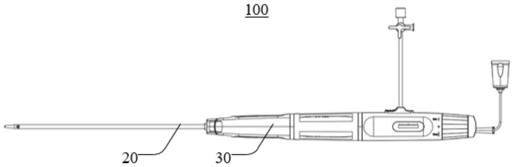
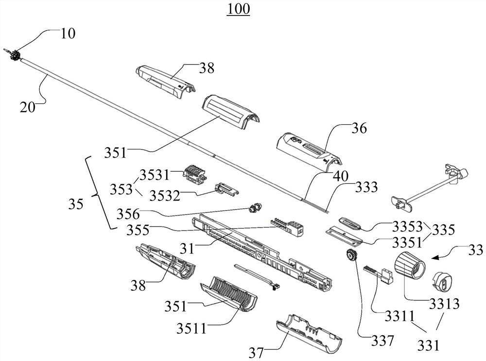
[0040] see figure 1 and figure 2 , figure 1 It is a three-dimensional schematic diagram of the stoma system provided in the first embodiment of the present application, figure 2 for figure 1 The three-dimensional exploded view of the ostomy system is shown. The ostomy system 100 includes an electrode holder 10 , a sheath tube assembly 20 and a handle 30 . The electrode bracket 10 is accommodated at the distal end of the sheath tube assembly 20, and the electrode bracket 10 establishes a shunt channel in the tissue at the stoma through expansion and ablation.

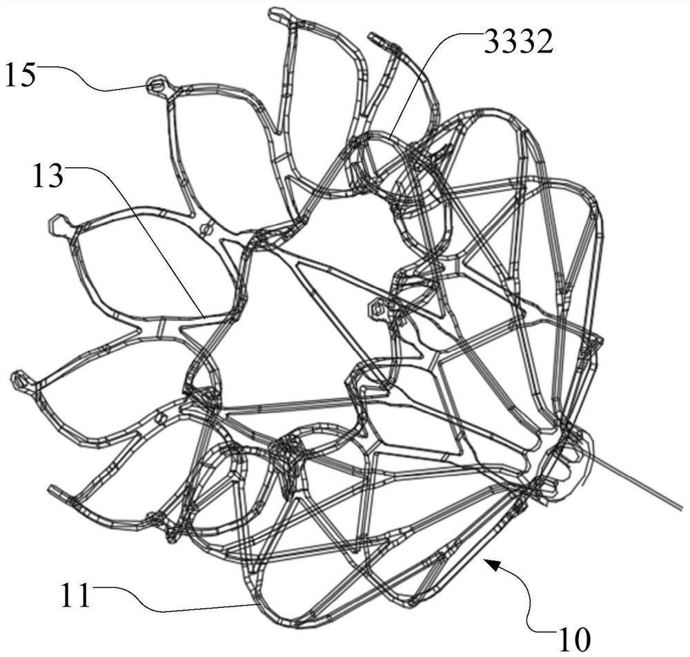
[0041] see image 3 , image 3 A three-dimensional schematic diagram of the electrode holder. The electrode holder 10 is released when it reaches the puncture site of the patient's stoma tissue, and an artificial "defect" is formed in the patient's stoma tissue through radiofrequency ablation. The electrode holder 10 includes a proximal portion 11 , a waist portion 13 and a distal portion 15 which are sequential...

no. 2 approach

[0123] see Figure 21-Figure 23 , Figure 21 It is a three-dimensional exploded schematic view of the stoma system 200 provided in the second embodiment of the present application. The structure of the stoma system 200 provided in the second embodiment of the present application is roughly similar to that of the stoma system 100 provided in the first embodiment. The difference is that please refer to Figure 24 As shown, the sheath tube joint structure 653 includes a sheath tube joint 6531 and a driving rack 6532 fixedly connected to each other, and the driving rack 6532 is set at a distance from the transmission structure 656 (such as Figure 25 and Figure 26 shown). In the initial state where there is no need to release the electrode bracket 201, the active rack 6532 is set at a distance from the transmission structure 656, the connecting part 6571 of the locking part 657 is pivotally connected to the main shaft 611, and the locking part 6575 of the locking part 657 is c...


PUM


Abstract

The invention discloses a stoma system, which comprises a handle, a sheathing canal component and an electrode support, wherein the electrode support is contained in the far end of the sheathing canal component and establishes a flow division channel for tissues on the stoma through an expansion and ablation function; the handle comprises a conveying device and a diameter regulation device, wherein the diameter regulation device comprises a diameter regulation structure and a diameter regulation line; the diameter regulation structure is fixed with the near end of the diameter regulation line; the diameter regulation line is movably penetrated in the conveying device and the sheathing canal component; the far end of the diameter regulation line is wound to the electrode support; and the diameter regulation structure is used for driving the diameter regulation line to move along the axial direction so as to regulate the diameter of the electrode support released from the sheathing canal component. Through the diameter regulation structure, the axial displacement of the diameter regulation line wound to the electrode support is controlled and regulated to regulate the diameter of the electrode support released from the sheathing canal component, and the size of the flow division channel is regulated according to different patient requirements so as to be favorable for improving the efficiency of stoma surgery.

Description

technical field [0001] The present application relates to the technical field of medical devices, in particular to an ostomy system. Background technique [0002] Heart failure (heart failure for short), is a complex clinical syndrome of impaired ventricular filling or ejection due to any structural or functional abnormality of the heart, the main clinical manifestations of which are dyspnea and fatigue (limited exercise tolerance), and Fluid retention (pulmonary congestion and peripheral edema). Heart failure is the severe and terminal stage of various heart diseases, with a high incidence rate, and is one of the most important cardiovascular diseases today. According to the location of heart failure, it can be divided into left heart failure, right heart failure and whole heart failure. [0003] Heart failure is a serious disease with high morbidity and mortality. The incidence of heart failure in my country is 2-3%, more than 12 million. The causes of heart failure ma...

Claims


Application Information

Patent Timeline
IPC IPC(8): A61B18/12A61B18/14A61F2/82A61F2/966A61F2/97
CPCA61B18/12A61B18/14A61B2018/00351A61B2018/00577A61F2/82A61F2/966A61F2/97
Inventor 高国庆王永胜
Owner HANGZHOU NOYA MEDTECH CO LTD
Why Eureka
Try Eureka