
Circular tuyere welding device

A welding device and tuyere technology, which is applied in the field of circular tuyere welding devices, can solve problems such as hidden safety hazards, high work intensity of workers, splash injury to workers, etc., and achieve the effect of increasing safety.

Inactive Publication Date: 2021-07-16
SHANGHAI YINDA AIR CONDITIONING ENTERPRISE
View PDF8 Cites 2 Cited by
  • Summary
  • Abstract
  • Description
  • Claims
  • Application Information

AI Technical Summary

Problems solved by technology

[0002] When assembling the round air outlet of the air conditioner, not only assembly is required, but also the frame of the air outlet needs to be welded to complete the assembly of the entire air outlet. Conventionally, manual assembly is used, and welding is carried out at the same time during the assembly process. The production efficiency At the same time, the work intensity of the workers is relatively high, and they are prone to fatigue, which creates potential safety hazards
[0003] The traditional circular tuyere welding device has the following disadvantages: 1. The traditional circular tuyere welding device needs manual welding, and the fixed torch welding has low welding flexibility and low intelligence, which increases the workload of the staff and makes the staff Very tired; 2. The traditional circular tuyere welding device does not have a protective device, and the staff needs to hold a mask for protection during welding. The welding slag is easy to spray out during welding, which is very dangerous to splash the staff; therefore, it is very dangerous for those skilled in the art to provide A circular tuyere welding device is proposed to solve the problems raised in the above-mentioned background technology

Method used


Image

  • Circular tuyere welding device
  • Circular tuyere welding device
  • Circular tuyere welding device

Examples


Embodiment Construction

[0024] The following will clearly and completely describe the technical solutions in the embodiments of the present invention with reference to the accompanying drawings in the embodiments of the present invention. Obviously, the described embodiments are only some, not all, embodiments of the present invention. Based on the embodiments of the present invention, all other embodiments obtained by persons of ordinary skill in the art without making creative efforts belong to the protection scope of the present invention.

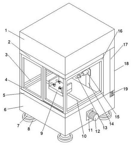
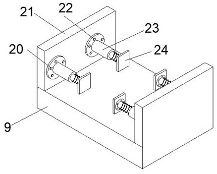
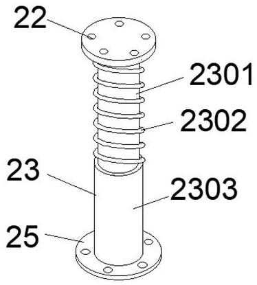
[0025] see Figure 1~6 , in an embodiment of the present invention, a circular tuyere welding device includes a lower seat 6, a worktable 9 is installed on the top of the lower seat 6, and side fixing plates 21 are fixedly connected to both sides of the top of the workbench 9, so that One side of the side wall of the side fixing plate 21 is detachably equipped with a telescopic column 23, and the end of the telescopic column 23 is detachably installed with a l...


PUM


Abstract

The invention discloses a circular tuyere welding device and belongs to the technical field of welding device. The circular tuyere welding device comprises a lower base, wherein a workbench is mounted at the top of the lower base; side fixing plates are fixedly connected to the two sides of the top of the workbench; telescopic columns are detachably mounted on one sides of the outer side walls of the side fixing plates; and limiting square pieces are detachably mounted at the tail ends of the telescopic columns. According to the circular tuyere welding device disclosed by the invention, a circular tuyere of an air conditioner can be intelligently and automatically welded, and a welding gun can be moved in the welding device in any direction of the X axis, the Y axis and the Z axis, so that the flexibility is high, manual welding is not needed, and manpower resources are saved; and the circular tuyere welding device disclosed by the invention is a closed welding device, observable glass windows are arranged on three faces, two sides are fixed, and the other side can slide in a double-track mode, so that observation during welding is facilitated, workers are protected from being splashed by welding slag, and the working safety is improved.

Description

technical field [0001] The invention relates to the field of welding devices, in particular to a circular tuyere welding device. Background technique [0002] When assembling the round air outlet of the air conditioner, not only assembly is required, but also the frame of the air outlet needs to be welded to complete the assembly of the entire air outlet. Conventionally, manual assembly is used, and welding is carried out at the same time during the assembly process. The production efficiency At the same time, the work intensity of the workers is relatively high, and they are prone to fatigue, which creates potential safety hazards. [0003] The traditional circular tuyere welding device has the following disadvantages: 1. The traditional circular tuyere welding device requires manual welding, and the fixed torch welding has low welding flexibility and low intelligence, which increases the workload of the staff and makes the staff Very tired; 2. The traditional circular tuy...

Claims


Application Information

Patent Timeline
IPC IPC(8): B23K37/02B23K37/04B23K37/00
CPCB23K37/0247B23K37/0252B23K37/0426B23K37/00
Inventor 唐小芳
Owner SHANGHAI YINDA AIR CONDITIONING ENTERPRISE
Learn More