
A mode-locked fiber laser

A fiber laser, mode-locking technology, applied in lasers, laser parts, phonon exciters, etc., can solve the problem of high mode-locking threshold, and achieve the effect of lowering the mode-locking threshold

Active Publication Date: 2022-05-03
NORTHWEST UNIV
View PDF8 Cites 0 Cited by
  • Summary
  • Abstract
  • Description
  • Claims
  • Application Information

AI Technical Summary

Problems solved by technology

[0004] The purpose of the present invention is to provide a parity time-symmetric mode-locked fiber laser based on the co-modulation of intensity and phase, to solve the problem that the mode-locked threshold of the existing mode-locked fiber laser is too high

Method used


Image

  • A mode-locked fiber laser
  • A mode-locked fiber laser

Examples


Embodiment 1

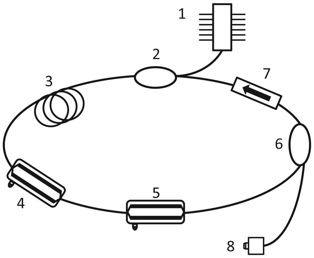
[0045] Such as figure 1 As shown, the embodiment of the present invention provides a mode-locked fiber laser, which includes a pump source 1 and a wavelength division multiplexer 2 connected in sequence, a doped fiber 3, an intensity modulator 4, a phase modulator 5, an output coupling device 6 and optical isolator 7, and the other end of the wavelength division multiplexer 2 is connected to the other end of the optical isolator 7 to form a ring cavity;

[0046] It is worth noting that all pump sources 1 in the present invention are polarization maintaining pump sources, and all wavelength division multiplexers 2 are polarization maintaining wavelength division multiplexers.

[0047] The pumping source 1 is connected to the wavelength division multiplexer 2 in the annular cavity;

[0048] The pump source 1 is used to emit pump light; the wavelength division multiplexer 2 is used to couple the pump source 1 and the light output by the optical isolator 7; the doped fiber 3 is s...

Embodiment 2

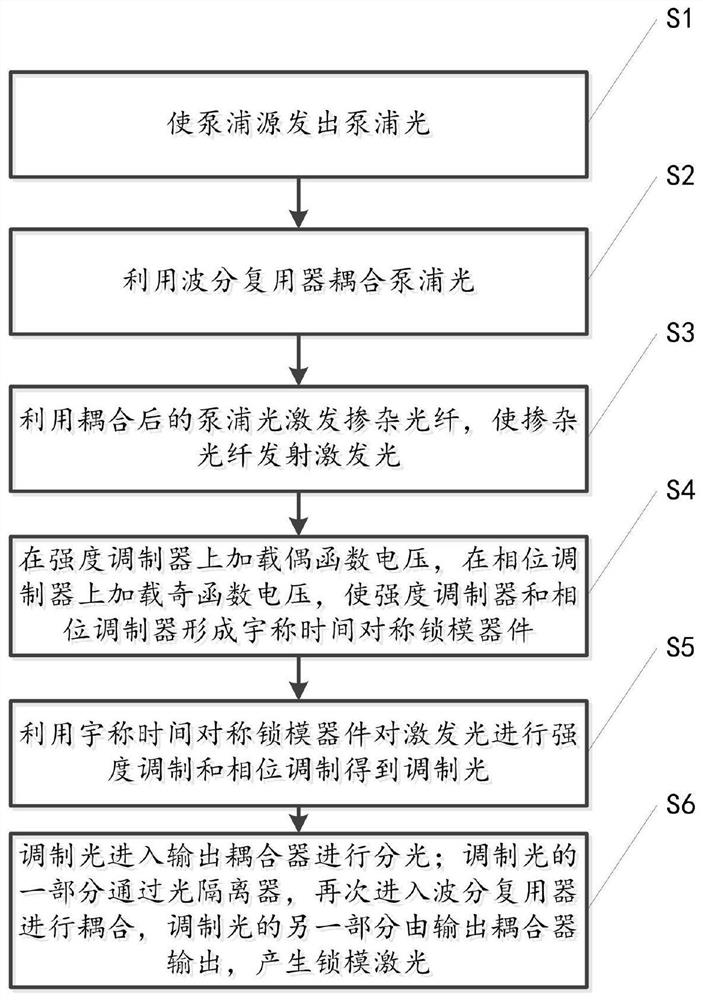
[0062] Such as figure 2 As shown, the embodiment of the present invention provides a method for adjusting a mode-locked fiber laser. The method is implemented using the mode-locked fiber laser provided in the first embodiment above. The specific steps include:

[0063] S1, making the pumping source 1 emit pumping light;

[0064] S2. Using a wavelength division multiplexer 2 to couple the pump light;

[0065] S3. Using the coupled pump light to excite the doped fiber 3, so that the doped fiber 3 emits excitation light;

[0066] S4. Apply an even function voltage to the intensity modulator 4, and apply an odd function voltage to the phase modulator 5, so that the intensity modulator 4 and the phase modulator 5 form a parity time-symmetrical mode-locking device;

[0067] Specifically, in the embodiment of the present invention, a dual-channel function generator is used to generate a voltage function signal as an external signal to drive the phase modulator 5 and the intensity ...


PUM

PropertyMeasurementUnit
wavelengthaaaaaaaaaa

Abstract

The invention relates to a mode-locked fiber laser, comprising a pump source, a wavelength division multiplexer, a doped fiber, an intensity modulator, a phase modulator, an output coupler and an optical isolator connected in sequence, and the wavelength division multiplexer has a The other end is connected to the other end of the optical isolator to form a ring cavity; through adjustment, the voltage function loaded on the intensity modulator is an even function, and the voltage function loaded on the phase modulator is an odd function, so that the intensity modulator and the The phase modulator as a whole forms a parity-time symmetric mode-locking device, which adjusts the intensity and phase at the same time, thereby reducing the mode-locking threshold of the mode-locked fiber laser. The peak and valley values ​​are equal in real time, so that the system is automatically in the state of parity time symmetry or parity time symmetry breaking state.

Description

technical field [0001] The invention relates to the field of fiber lasers and parity time symmetric optics, in particular to a parity time symmetry mode-locked fiber laser based on intensity and phase co-modulation. Background technique [0002] Due to the advantages of short pulse duration, high peak power, wide spectral bandwidth, and good mechanical properties, mode-locked fiber lasers play an important role in the fields of transient optics, optical communication and information processing, optical fiber sensing, medical diagnosis, and material processing. Applications. [0003] In mode-locked lasers, the mode-locked threshold and tunable performance are two important indicators to measure the performance of mode-locked lasers. In the existing mode-locked fiber laser, the loss caused by coupling between fiber devices reduces the effective gain bandwidth, increases the mode-locking threshold of the laser, and reduces the pulse width and spectral tuning range of the laser...

Claims


Application Information

Patent Timeline
Patent Type & Authority Patents(China)
IPC IPC(8): H01S3/067H01S3/094H01S3/10H01S3/098
CPCH01S3/10053H01S3/10H01S3/06791H01S3/06716H01S3/1109H01S3/094053
Inventor 陆宝乐吕辰悦白晋涛陈浩伟
Owner NORTHWEST UNIV
Learn More