
A negative pressure vibrating screen

A vibrating screen and negative pressure technology, which is applied in the field of screening treatment equipment, can solve the problems of poor separation and treatment of drilling fluid, and achieve the effect of ensuring continuous operation, good integrity and improving efficiency

Active Publication Date: 2022-08-09
广汉市阿里圣姆石油设备有限公司 +1
View PDF19 Cites 0 Cited by
  • Summary
  • Abstract
  • Description
  • Claims
  • Application Information

AI Technical Summary

Problems solved by technology

[0003] The invention aims at the problem of poor drilling fluid separation and treatment effect in the prior art, and provides a negative pressure vibrating screen

Method used


Image

  • A negative pressure vibrating screen
  • A negative pressure vibrating screen
  • A negative pressure vibrating screen

Examples


Embodiment Construction

[0044] In order to make the purposes, technical solutions and advantages of the embodiments of the present invention clearer, the technical solutions in the embodiments of the present invention will be clearly and completely described below with reference to the accompanying drawings in the embodiments of the present invention. Obviously, the described embodiments These are some embodiments of the present invention, but not all embodiments.

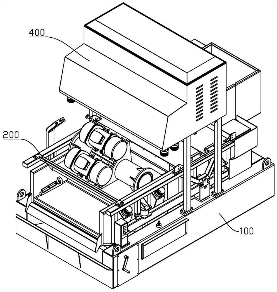
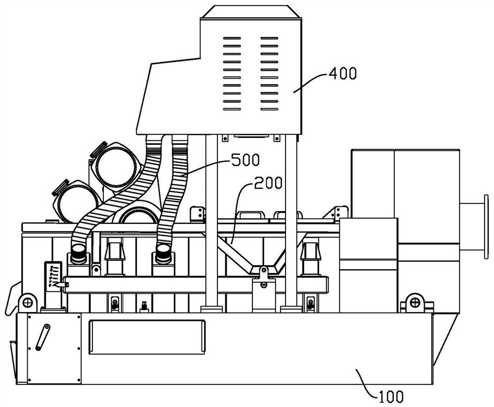
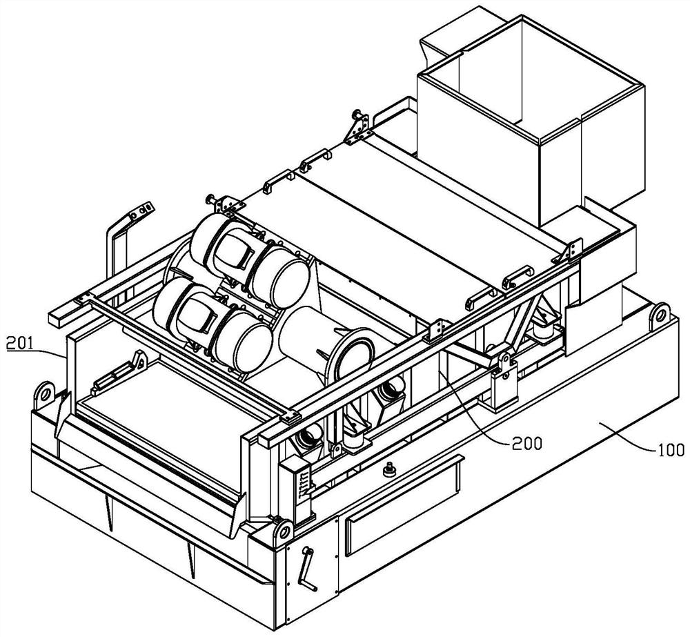
[0045] like Figures 1 to 5 As shown, the negative pressure vibrating screen in this embodiment includes a base 100 and a screen box assembly 200 arranged on the base; the screen box assembly 200 includes a box body 201 and a plurality of screen meshes 203 arranged in the box body, so The screens 203 are arranged side by side in sequence from the feed end to the discharge end.

[0046] like Image 6, a vacuum chamber 204 is respectively arranged under the two screens 203 on the side of the discharge end, and the vacuum chamber 204 has a...


PUM


Abstract

The invention discloses a negative pressure vibrating screen, comprising a base and a screen box assembly arranged on the base; the screen box assembly includes a box body and a plurality of screen meshes arranged in the box body, the screen meshes extending from the inlet The material ends are arranged side by side toward the discharge end in sequence; a vacuum chamber is arranged under at least one screen on the side close to the discharge end, and a liquid discharge port is arranged at the bottom of the vacuum chamber; The shut-off box is located below the vacuum chamber, and the liquid discharge port of the vacuum chamber is connected to the liquid inlet of the shut-off box. By designing the structure of the interception box, the liquid level formed in the interception box is used to seal and isolate the liquid inlet and the liquid outlet, and the vacuum chamber is formed into a sealed cavity, so that a negative pressure can be formed in the vacuum chamber. At the same time, the separated liquid can be continuously drained to ensure the continuous operation of the equipment and greatly improve the processing efficiency of the equipment.

Description

technical field [0001] The invention relates to the technical field of screening treatment equipment, in particular to a negative pressure vibrating screen used for drilling fluid recovery and treatment. Background technique [0002] The existing solid phase control technology for oil drilling generally uses vibrating screening to remove most of the drilling cuttings carried from the drilling fluid returned from the well. The loss of drilling cuttings is large, the subsequent environmental protection treatment of drill cuttings is heavy, and the treatment cost is high. In order to reduce the liquid content of the separated drill cuttings, many companies around the world have carried out research on related technologies, such as drilling fluid solid-liquid separation equipment based on vacuum filtration continuous circulating screens, drilling fluid separation devices based on pulse vacuum, and Vibrating screening device based on pulsating negative pressure, etc. The vibrat...

Claims


Application Information

Patent Timeline
Patent Type & Authority Patents(China)
IPC IPC(8): B01D33/03B01D33/35B01D33/74B01D33/80
CPCB01D33/0346B01D33/35B01D33/74B01D33/80B01D33/804B01D33/808B01D2201/204Y02P70/10
Inventor 任万年谭劲
Owner 广汉市阿里圣姆石油设备有限公司
Learn More