Device and method for treating landfill leachate membrane separation concentrated solution through surface photo-thermal evaporation

A technology for landfill leachate and membrane separation, which can be applied in illumination water/sewage treatment, heating water/sewage treatment, water/sewage treatment, etc. problem, to achieve the effect of increasing the light intensity, accelerating the surface evaporation rate, and enhancing the surface evaporation rate

Pending Publication Date: 2021-07-23
HUAZHONG UNIV OF SCI & TECH
View PDF3 Cites 1 Cited by
  • Summary
  • Abstract
  • Description
  • Claims
  • Application Information

AI Technical Summary

Problems solved by technology

However, these methods may result in discontinuity of operation or inefficiency in water vapor generation
Additionally, highly concentrated salts diffuse back into solution instead of being harvested, wasting the opportunity to gain access to valuable mineral resources

Method used


Image

  • Device and method for treating landfill leachate membrane separation concentrated solution through surface photo-thermal evaporation
  • Device and method for treating landfill leachate membrane separation concentrated solution through surface photo-thermal evaporation

Examples


Embodiment 1

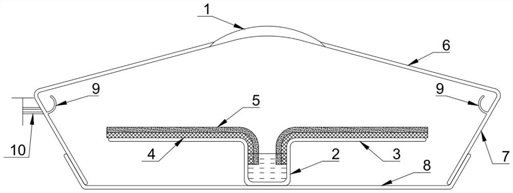
[0037] The present invention is a device for treating landfill leachate film concentrate by surface photothermal evaporation, such as figure 1 As shown, it includes a condenser 1, a reaction pool 2, an evaporation table 3, a hydrophilic porous material layer 4, a photothermal porous material layer 5, an inclined transparent condensation top cover 6, a transparent side wall 7, a crystal salt collection box 8, and a condensation water collection Groove 9, condensed water outlet 10.

[0038] The condenser lens 1 is embedded in the inclined transparent condensation top cover 6; the inclined transparent condensation top cover 6 and the transparent side wall 7 are placed above the crystallization salt collection box 8; the reaction pool 2 is placed in the crystallization salt collection box 8; The evaporation table 3 is located on the edge of the reaction pool 2, and the evaporation table 3 is sequentially attached with a hydrophilic porous material layer 4 and a photothermal porous...

Embodiment 2

[0042] The present invention is a device for treating landfill leachate film concentrate by surface photothermal evaporation, such as figure 1 As shown, it includes a condenser 1, a reaction pool 2, an evaporation table 3, a hydrophilic porous material layer 4, a photothermal porous material layer 5, an inclined transparent condensation top cover 6, a transparent side wall 7, a crystal salt collection box 8, and a condensation water collection Groove 9, condensed water outlet 10.

[0043] The condenser lens 1 is embedded in the inclined transparent condensation top cover 6; the inclined transparent condensation top cover 6 and the transparent side wall 7 are placed above the crystallization salt collection box 8; the reaction pool 2 is placed in the crystallization salt collection box 8; The evaporation table 3 is located on the edge of the reaction pool 2, and the evaporation table 3 is sequentially attached with a hydrophilic porous material layer 4 and a photothermal porous...

Embodiment 3

[0050] The present invention is a device for treating landfill leachate film concentrate by surface photothermal evaporation, such as figure 1 As shown, it includes a condenser 1, a reaction pool 2, an evaporation table 3, a hydrophilic porous material layer 4, a photothermal porous material layer 5, an inclined transparent condensation top cover 6, a transparent side wall 7, a crystal salt collection box 8, and a condensation water collection Groove 9, condensed water outlet 10.

[0051] The condenser lens 1 is embedded in the inclined transparent condensation top cover 6; the inclined transparent condensation top cover 6 and the transparent side wall 7 are placed above the crystallization salt collection box 8; the reaction pool 2 is placed in the crystallization salt collection box 8; The evaporation table 3 is located on the edge of the reaction pool 2, and the evaporation table 3 is sequentially attached with a hydrophilic porous material layer 4 and a photothermal porous...


PUM


Abstract

The invention relates to a device and a method for treating a landfill leachate membrane separation concentrated solution through surface photo-thermal evaporation, and belongs to the technical field of landfill leachate membrane concentrated solution treatment. The device comprises a condensing lens, a reaction tank, an evaporation table, a hydrophilic porous material layer, a photo-thermal porous material layer, an inclined transparent condensation top cover, a transparent side wall, a crystal salt collection box, a condensate water collection tank and a condensate water outlet, the condensing lens is embedded into the inclined transparent condensing top cover; the inclined transparent condensation top cover and the transparent side wall are arranged above the crystal salt collecting box in a covering mode; the reaction tank is arranged in the crystal salt collecting box; the evaporation table is located at the edge of the reaction tank, the hydrophilic porous material layer and a photo-thermal porous material layer are sequentially attached to the evaporation table from bottom to top, and the hydrophilic porous material layer extends to the side wall of the reaction tank; the condensate water collection tank is located around the inner wall of the transparent side wall. Air internal circulation exists in the reactor, air convection on the surface of the photo-thermal material is promoted, and the surface evaporation rate of the photo-thermal material is increased.

Description

technical field [0001] The invention belongs to the technical field of treatment of landfill leachate membrane concentrate, and more specifically relates to a device and method for surface photothermal evaporation treatment of landfill leachate membrane separation concentrate. Background technique [0002] With the continuous development of my country's urban economy, the expansion of urban scale, and the substantial improvement of residents' living standards, the total amount of urban garbage generated is increasing at an average annual rate of 8% to 10%. In 2018, the national domestic waste removal volume reached 228 million tons. According to estimates, my country will add about 400 million tons of municipal waste in 2030, and about 500 million tons in 2050. The problem of waste disposal has become increasingly prominent. Sanitary landfill is the most traditional and main way to dispose of garbage in my country and most other countries, and the method is simple. The dis...

Claims


Application Information

Patent Timeline
Patent Type & Authority Applications(China)
IPC IPC(8): C02F9/10C02F1/04C02F1/14C02F103/06C02F101/30
CPCC02F1/043C02F1/048C02F1/14C02F1/281C02F1/30C02F9/00C02F2101/30C02F2103/06C02F2305/10Y02A20/212
Inventor 权俊达史伊蒙郭晓姜惕明叶轲夫刘杰李想唐荣宋一笑袁书珊梁莎胡敬平侯慧杰苗蕾刘冰川杨家宽张战
Owner HUAZHONG UNIV OF SCI & TECH
Why Eureka
Try Eureka