Magnet component, magnetron sputtering cathode and magnetron sputtering device for flexible wire coating

A technology of magnetron sputtering device and magnet components, which is applied in the direction of sputtering coating, ion implantation coating, vacuum evaporation coating, etc., can solve the problems without too much explanation, achieve improvement effect, increase utilization rate, uniform The effect of coating

Active Publication Date: 2021-07-23
LUOYANG INST OF SCI & TECH
View PDF20 Cites 0 Cited by
  • Summary
  • Abstract
  • Description
  • Claims
  • Application Information

AI Technical Summary

Problems solved by technology

Both of the above two devices can realize the magnetron sputtering coating of flexible wires, but there is not too much description on the structure and setting method of the magnetron sputtering cathodes, because the outer surface of the flexible wires is a rotating surface, and the magnetron sputtering cathodes are Plane, so that the structure

Method used


Image

  • Magnet component, magnetron sputtering cathode and magnetron sputtering device for flexible wire coating
  • Magnet component, magnetron sputtering cathode and magnetron sputtering device for flexible wire coating
  • Magnet component, magnetron sputtering cathode and magnetron sputtering device for flexible wire coating

Examples


Embodiment 1

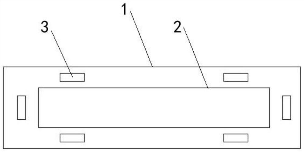
[0032] Such as figure 1 Shown: a magnet component, including an outer magnet 1 , an inner magnet 2 and six auxiliary magnets 3 . Both the outer magnet 1 and the inner magnet 2 have a rectangular ring structure, the inner magnet 2 is located inside the outer magnet 1 and the installation polarity of the two is opposite, and six auxiliary magnets 3 are arranged in the annular gap between the outer magnet 1 and the inner magnet 2, The outer magnet 1 and the inner magnet 2 are permanent magnets, and the auxiliary magnet 3 is an electromagnet. Wherein, the outer magnet 1 and the inner magnet 2 constitute the main magnetic field of the magnet component, and since the outer magnet 1 and the inner magnet 2 are permanent magnets, the main magnetic field is a stable magnetic field. The addition of the auxiliary magnet 3 can generate an auxiliary magnetic field, which can interfere with the main magnetic field and change the magnetic field environment of the magnet components. The auxi...

Embodiment 2

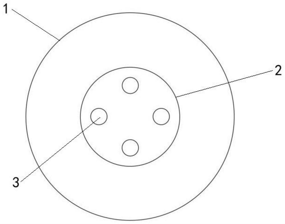
[0034] Such as figure 2 Shown: a magnet component, including an outer magnet 1 , an inner magnet 2 and four auxiliary magnets 3 . Both the outer magnet 1 and the inner magnet 2 are circular structures, the inner magnet 2 is located inside the outer magnet 1 and the installation polarity of the two is opposite, two auxiliary magnets 3 are arranged inside the inner magnet 2, the outer magnet 1 and the inner magnet 2 It is a permanent magnet, and the auxiliary magnet 3 is an electromagnet. Wherein, the outer magnet 1 and the inner magnet 2 constitute the main magnetic field of the magnet component, and since the outer magnet 1 and the inner magnet 2 are permanent magnets, the main magnetic field is a stable magnetic field. The addition of the auxiliary magnet 3 can generate an auxiliary magnetic field, which can interfere with the main magnetic field and change the magnetic field environment of the magnet components. The auxiliary magnet 3 is made of an iron core and a coil wo...

Embodiment 3

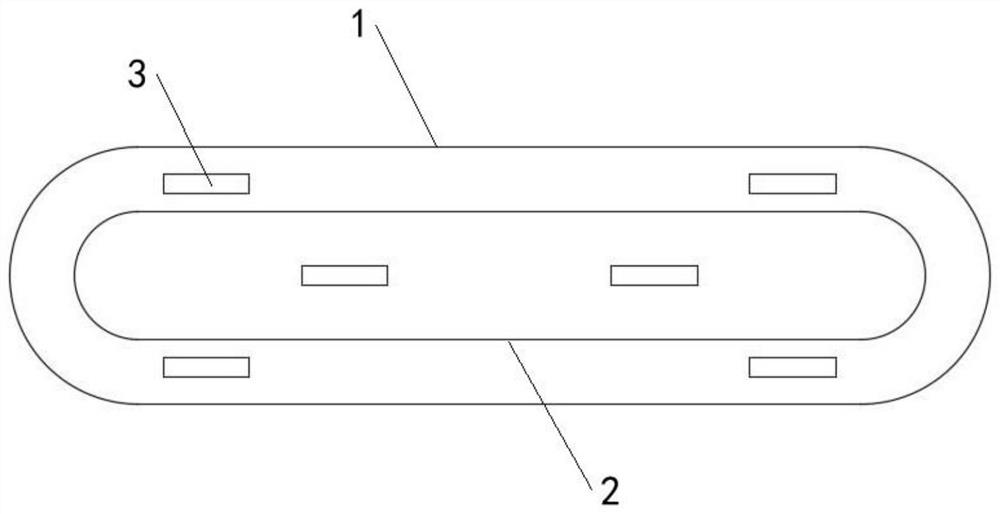
[0036]Such as image 3 Shown: a magnet component, including an outer magnet 1 , an inner magnet 2 and six auxiliary magnets 3 . The outer magnet 1 and the inner magnet 2 are both racetrack-shaped structures, the inner magnet 2 is located inside the outer magnet 1 and the installation polarities of the two are opposite, of which 2 auxiliary magnets 3 are arranged inside the inner magnet 2, and the remaining 4 auxiliary magnets 3 are arranged In the annular gap between the outer magnet 1 and the inner magnet 2, the outer magnet 1 and the inner magnet 2 are permanent magnets, and the auxiliary magnet 3 is an electromagnet. The upper surfaces of the outer magnet 1 and the inner magnet 2 are curved surfaces, which are suitable for the curvature of the water-cooled back plate 6 . Wherein, the outer magnet 1 and the inner magnet 2 constitute the main magnetic field of the magnet component, and since the outer magnet 1 and the inner magnet 2 are permanent magnets, the main magnetic f...


PUM


Abstract

Disclosed are a magnet component, a magnetron sputtering cathode and a magnetron sputtering device for flexible wire coating. The magnetron sputtering device comprises a roller releasing part, a coating part and a roller collecting part, wherein at least two magnetron sputtering cathodes are arranged in the coating part in the moving direction of a flexible wire. An auxiliary magnet power line of each magnetron sputtering cathode is connected to a first contact and a second contact, a driving shaft is in transmission connection with a rotating disc, a conductive piece capable of conducting the first contact and the second contact is arranged on the rotating disc, in the rotating process of the rotating disc, the position relation between the conductive piece and the first contact and the position relation between the conductive piece and the second contact change intermittently, and intermittent power supply of the auxiliary magnet is finally realized. The magnetron sputtering cathode disclosed by the invention is provided with the adjustable and variable auxiliary magnet, the magnetic field intermittently generated by the auxiliary magnet can generate an intermittent interference effect with the magnetic fields generated by an outer magnet and an inner magnet, the unbalance degree of the magnetic field can be adjusted, the sputtering coating effect can be improved, a more uniform coating can be obtained, and the utilization rate of a target material can also be improved.

Description

technical field [0001] The invention relates to the technical field of magnetron sputtering coating, in particular to a magnetron sputtering device for a magnet component, a magnetron sputtering cathode and a flexible wire coating. Background technique [0002] Due to the needs of the development of modern science and technology, vacuum coating technology has developed rapidly. Thin film technology can change the surface properties of the workpiece, improve the wear resistance, oxidation resistance, corrosion resistance and other properties of the workpiece, and prolong the service life of the workpiece, which has high economic value. Thin film technology can meet the requirements of new materials for special use conditions and functions. Magnetron sputtering technology can prepare superhard films, corrosion-resistant friction films, superconducting films, magnetic films, optical films, and various films with special functions. It is a very effective film deposition method ...

Claims


Application Information

Patent Timeline
IPC IPC(8): C23C14/35C23C14/54C23C14/56
CPCC23C14/35C23C14/54C23C14/562
Inventor 胡鹏飞赵利国贾贵西尹国杰孙要梅范吉昌李开勇李治国
Owner LUOYANG INST OF SCI & TECH
Why Eureka
Try Eureka