Pile body (or column body) concrete vibrating rod lifting device and construction method thereof

A technology of concrete and vibrating rods, which is applied in sheet pile walls, foundation structure engineering, erection/assembly of bridges, etc., can solve the problems of large safety hazards and low efficacy, and achieve the effects of eliminating air bubbles, fast speed, and improving construction efficiency

Active Publication Date: 2021-07-23
CCCC SECOND HARBOR ENG
View PDF5 Cites 2 Cited by
  • Summary
  • Abstract
  • Description
  • Claims
  • Application Information

AI Technical Summary

Problems solved by technology

[0006] The main purpose of the present invention is to provide a pile column body concrete vibrator lifting device and its construction method to solve the problem that bridge pile concrete needs to be vibrated once every 30cm in order to ensure the compactness, and the concrete vibrator needs to climb up and down every 30cm to vibrate. Pound once, the effect is extremely low, and the problem of great safety hazard

Method used


Image

  • Pile body (or column body) concrete vibrating rod lifting device and construction method thereof
  • Pile body (or column body) concrete vibrating rod lifting device and construction method thereof
  • Pile body (or column body) concrete vibrating rod lifting device and construction method thereof

Examples


Embodiment 1

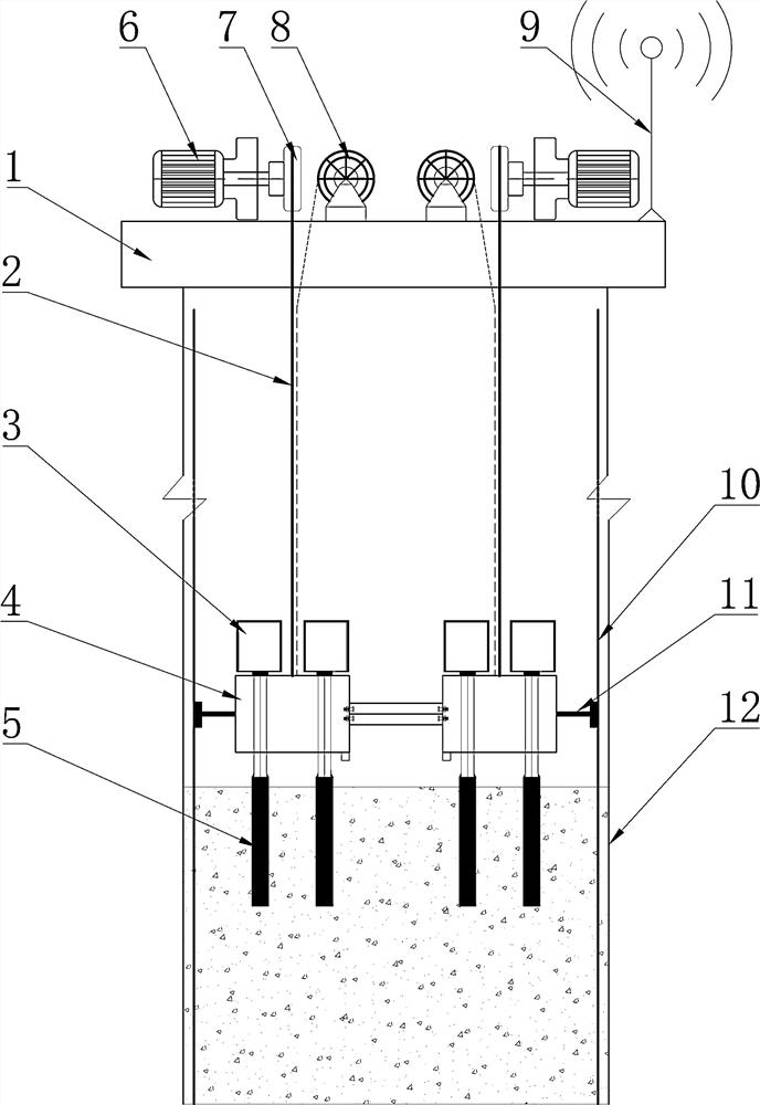
[0039] Such as Figure 1~4 As shown, the lifting device for the concrete vibrating rod of the pile body includes a beam 1, which is used to place the opening position above the formwork frame 12. The beam 1 is provided with a plurality of winches 6, and is also provided with a plurality of counterweight vibrating platforms 4 , the winch 6 is connected with the counterweight vibrating platform 4 through the lifting rope 2, and the counterweight vibrating platform 4 is provided with a plurality of vibrating motors 3, and the vibrating motors 3 are connected with the vibrating rod 5, and the two adjacent counterweights vibrate The pounding platform 4 is connected by a connecting rod 15, and one side of the counterweight vibrating platform 4 is also provided with a stabilizing device 11. Design the counterweight vibrating platform 4, place two vibrating motors 3 on the counterweight vibrating platform 4, and set the two vibrating rods 5 at the bottom of the vibrating platform acco...

Embodiment 2

[0049] Further illustrate in conjunction with embodiment 1, as Figure 1-4 As shown in the structure, the stabilizing device 11 and the formwork frame 12 have been constructed according to the drawings.

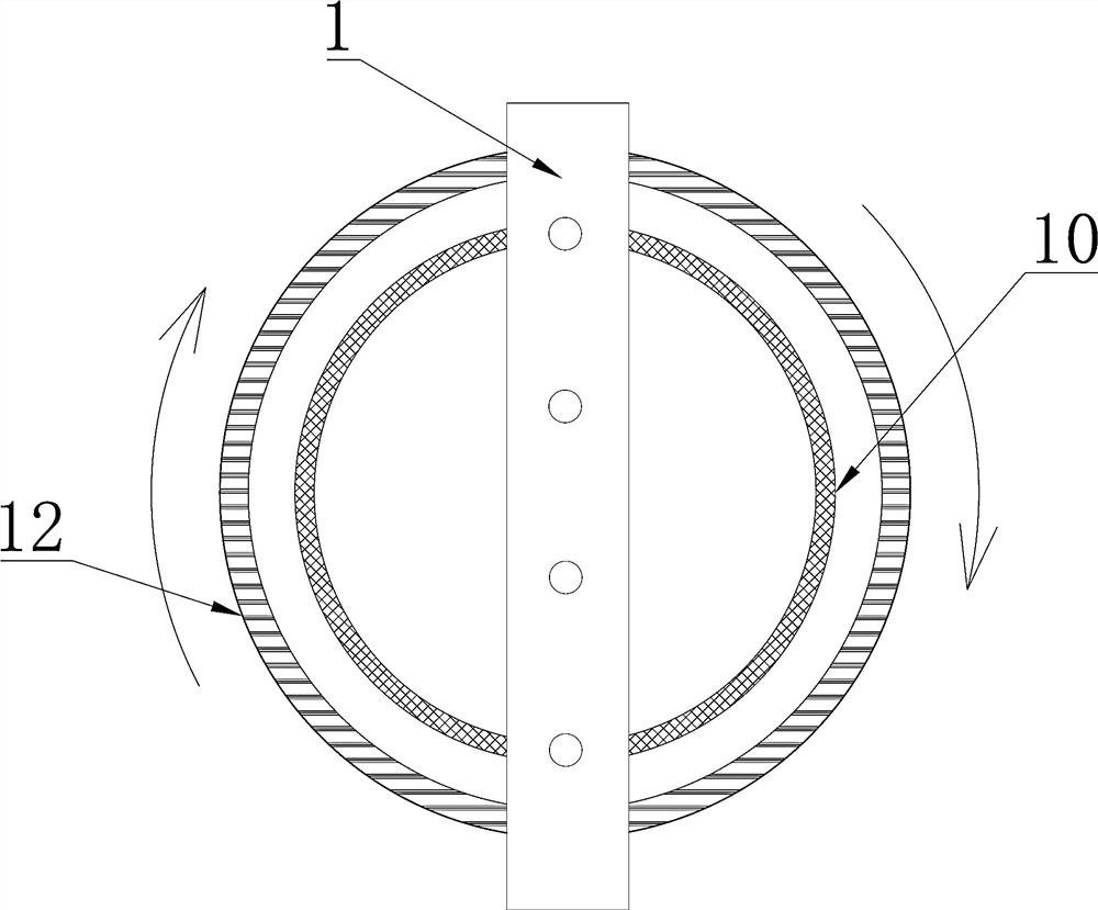
[0050] The crossbeam 1 is hoisted at the opening position of the formwork frame 12 , and the entire counterweight vibrating platform 4 is placed inside the steel cage 10 , and the adjacent counterweight vibrating platforms 4 are connected by connecting rods 15 .

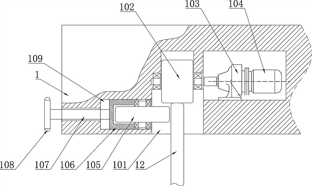
[0051] Place the rollers 102 inside the groove body 101 of the beam 1 on the formwork frame 12 .

[0052] Adjust the crossbeam 1, and adjust the adjustment rollers 105 at both ends of the crossbeam 1 against the outer surface of the formwork frame 12 so that the middle part of the crossbeam 1 is coaxial with the formwork frame 12.

[0053] By rotating the adjusting handle 108 , the adjusting roller 105 abuts against the outer surface of the formwork frame 12 .

[0054] The hoist 6 is controlled to rotate to lower ...


PUM


Abstract

The invention provides a pile body (or column body) concrete vibrating rod lifting device and a construction method thereof. A cross beam is used for being placed at the opening position above a formwork frame; a plurality of winches and a plurality of counterweight vibrating platforms are arranged on the cross beam; the winches are connected with the counterweight vibrating platforms through lifting ropes; a plurality of vibrating motors are arranged on the counterweight vibrating platforms; the vibrating motors are connected with vibrating rods; and every two adjacent counterweight vibrating platforms are connected through a connecting rod. By using the device, manual descending for vibrating operation can be avoided, the safety risk of a conventional vibrating process is avoided, and compared with conventional manual descending for vibrating, the concrete pouring and vibrating time is shortened, and the construction efficiency is greatly improved. The vertical and full-section vibrating range of concrete can be effectively controlled by controlling the wellhead winch and changing the position of the wellhead cross beam, the construction quality of pile body or column body concrete is ensured, and the device has high popularization value in terms of safety, quality and efficacy.

Description

technical field [0001] The invention relates to the field of longitudinal pushing of beam bodies, in particular to a lifting device for concrete vibrating rods of pile columns and a construction method thereof. Background technique [0002] During the pile (column) construction of expressway bridge engineering, in order to ensure the quality of concrete construction, it is necessary to manually go down the well for vibration. No matter on the top of the pile or the top of the column, the concrete vibrator climbing up and down along the steel cage is an ultra-high-risk operation. In order to ensure the compactness of bridge piles (columns), the concrete needs to be vibrated once every 30cm, and the concrete vibrator needs to climb up and down to vibrate once every 30cm, which has extremely low efficiency and great potential safety hazards. [0003] Chinese patent CN111350133A "Vibration device and method for bridge pier column" is used for the vibration device and method of b...

Claims


Application Information

Patent Timeline
IPC IPC(8): E02D5/34E02D15/04E01D21/00
CPCE02D5/34E02D15/04E01D21/00
Inventor 姜永生于得安周范武张国庆张芙蓉吕双江罗毅曾小可
Owner CCCC SECOND HARBOR ENG
Why Eureka
Try Eureka