Supercharge Your Innovation With Domain-Expert AI Agents!

Pneumatic control device for buried pipe in goaf and using method

A goaf and pneumatic technology, applied in the direction of mining equipment, valve equipment, safety equipment, etc., can solve the problems of potential safety hazards, and achieve the effect of saving the process of cutting buried pipes, low cost, and easy operation

Pending Publication Date: 2021-07-23
CCTEG SHENYANG RES INST
View PDF0 Cites 0 Cited by
  • Summary
  • Abstract
  • Description
  • Claims
  • Application Information

AI Technical Summary

Problems solved by technology

[0002] In the coal mining face with "U" ventilation, the upper corner is the place where gas is most likely to accumulate, posing potential safety hazards

Method used


Image

  • Pneumatic control device for buried pipe in goaf and using method

Examples


Embodiment 1

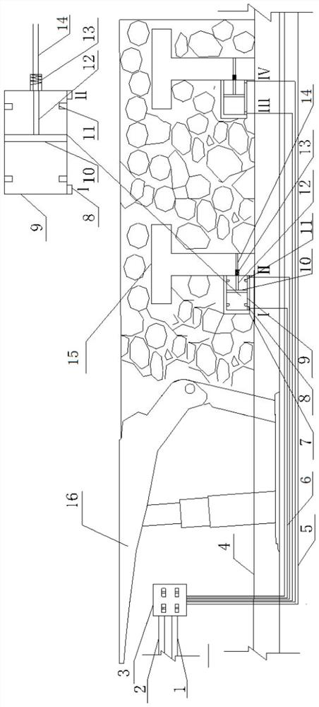
[0024] Such as figure 1 As shown, this embodiment proposes a goaf buried pipe pneumatic control device, including a pneumatic pressure control device, a pneumatic switching device, a T-shaped buried pipe 15 and a low negative pressure gas drainage pipeline 4, wherein the T-shaped buried pipe The output port of 15 is connected with the low negative pressure gas drainage pipeline 4. The pneumatic switching device includes a pneumatic valve 9, a pneumatic sliding plate 10, a baffle plate 14 and a linkage mechanism. The pneumatic valve 9 has a cavity inside, and the pneumatic sliding plate 10 can be slidably installed Inside the pneumatic valve 9, the pneumatic slide plate 10 divides the interior of the pneumatic valve 9 into a first pneumatic chamber and a second pneumatic chamber. The device can drive the pneumatic sliding plate 10 to slide in the pneumatic valve 9 by adjusting the air pressure in the first pneumatic chamber and the second pneumatic chamber, and the baffle 14 is...

Embodiment 2

[0032] This embodiment proposes a method for using the goaf buried pipe pneumatic control device, using the goaf buried pipe pneumatic control device in Embodiment 1, including the following steps,

[0033] Step 1. Connect the pneumatic valve 9 control switch 3 in the pneumatic pressure control device to the first pneumatic chamber and the second pneumatic chamber of the pneumatic switching device through the air guide tube 6, and place the baffle plate 14 in the low negative pressure gas drainage pipeline 4 and the junction of the T-shaped buried pipe 15;

[0034] Step 2. When installing and connecting the T-shaped buried pipe 15, install the baffle plate 14 inside it, install the pneumatic valve 9 on the side wall of the T-shaped buried pipe 15, and connect the air guide pipe 6 with the outlet and the air guide port 8;

[0035] Step 3. Control the switch 3 to switch the pressure difference between the first pneumatic chamber and the second pneumatic chamber by switching the ...

Embodiment 3

[0037] In combination with Embodiment 1 and Embodiment 2, this embodiment describes in detail the specific structure and usage method of the goaf buried pipe pneumatic control device.

[0038] First, when installing and connecting the T-shaped buried pipe 15, a baffle plate 14 is installed inside it, and the downhole pressure inlet air pipe 1 and the downhole pressure return air pipe 2 are connected with the pneumatic valve 9 control switch 3; the pneumatic valve 9 control switch 3 and The air guide tube 6 is connected, the air guide tube 6 is placed in the protective tube 5, the protective tube 5 is placed under the low negative pressure gas extraction pipe, the T-shaped buried pipe 15 is connected with the low negative pressure gas extraction tube, and the The air guide tube 6 is led out from the protective tube 5 and connected with the air guide port 8 of the pneumatic valve 9, the pneumatic valve 9 is connected with the baffle plate 14, and the protective shell 7 is install...


PUM


Abstract

The invention relates to the technical field of buried pipe extraction in a goaf of an underground coal mine, in particular to a pneumatic control device for a buried pipe in the goaf. The pneumatic control device for the buried pipe in the goaf is characterized in that an output port of a T-shaped buried pipe is in butt joint with a low-negative-pressure gas extraction pipeline, a cavity is formed in a pneumatic valve, and a pneumatic sliding plate is slidably mounted in the pneumatic valve; the pneumatic sliding plate divides the inner part of the pneumatic valve into a first pneumatic chamber and a second pneumatic chamber, a pneumatic pressure control device communicates with the first pneumatic chamber and the second pneumatic chamber through air guiding pipes, and the pneumatic pressure control device can drive the pneumatic sliding plate to slide in the pneumatic valve by adjusting the air pressure in the first pneumatic chamber and the air pressure in the second pneumatic chamber; a baffle is arranged at the communication position of the T-shaped buried pipe and the low-negative-pressure gas extraction pipeline, the pneumatic sliding plate is connected with the baffle through a linkage mechanism, and the pneumatic sliding plate switches the state of the baffle through the linkage mechanism. The pneumatic control device for the buried pipe in the goaf, it can be ensured that the buried pipe continuously extracts gas at the upper corner of the goaf. The invention further provides a using method of the pneumatic control device for the buried pipe in the goaf.

Description

technical field [0001] The patent of the present invention relates to the technical field of buried pipe drainage in underground goafs of coal mines, in particular to a pneumatic control device for buried pipes in goafs and a method of use thereof. Background technique [0002] In the coal mining face with "U" ventilation, the upper corner is the place where gas is most likely to accumulate, posing potential safety hazards. The goaf buried pipe drainage technology is a local auxiliary drainage measure for a specific range of the upper corner of the mining face. gas. The specific construction is to lay thin-walled steel pipes (wall thickness 3-5mm) in the goaf, and weld T-shaped vertical pipes at the ends of the steel pipes. The extraction branch pipe is connected. When the T-shaped buried pipe enters the goaf for 5m, the buried pipe is opened through the butterfly valve for drainage. When the length of the thin-walled steel pipe laid in the goaf exceeds 30m, the steel pipe...

Claims


Application Information

Patent Timeline
Patent Type & Authority Applications(China)
IPC IPC(8): E21F7/00E21F17/10F16K11/044F16K27/02F16K31/12
CPCE21F7/00E21F17/10F16K11/044F16K31/12F16K27/0263
Inventor 雷云孙亮贾男刘飞高宏烨邹永洺梁忠秋刘扬闫循强潘竞涛张辉迟羽淳董强
Owner CCTEG SHENYANG RES INST
Features
  • R&D
  • Intellectual Property
  • Life Sciences
  • Materials
  • Tech Scout
  • Unparalleled Data Quality
  • Higher Quality Content
  • 60% Fewer Hallucinations
Learn More