Reciprocating plunger type polymer injection pump fluid end

A technology of polymer injection pump and hydraulic end, which is applied in the field of polymer injection equipment for tertiary oil recovery process in oil fields, can solve the problems of liquid cylinder block scrapping, hidden dangers, high difficulty, etc., so as to reduce maintenance difficulty and labor intensity, prolong service life, guarantee Effectiveness

Pending Publication Date: 2021-07-23
宝鸡航天动力泵业有限公司
View PDF0 Cites 0 Cited by
  • Summary
  • Abstract
  • Description
  • Claims
  • Application Information

AI Technical Summary

Problems solved by technology

[0003] The liquid end of the existing polymer injection pump usually adopts a vertical structure, the valve assembly adopts a ball valve structure, and the valve spring cover adopts a porous structure at the top; there are the following defects: due to the limitation of the structure and performance of the ball valve itself, it is impossible to realize large flow of polymer; Due to the porous structure of the valve cover, the shear rate of the polymer is greatly increased, resulting in a decrease in viscosity, which greatly affects the oil displacement effect of the polymer; the valve group repeatedly knocks on the valve seat during normal operation. There is an interference fit between the valve seat and the cylinder body assembly, and it is difficult to replace the valve seat if it is damaged during use. ; The front end opening of the liquid cylinder body is equipped with a front gland, and the liquid cylinder body is processed to form a cross hole. This structure is prone to cracking when the cross hole is subjected to alternating stress during the working process of the polymer injection pump, and there is a major safety hazard. ; The liquid cylinder body and the suction pipe are of an integrated structure, and the suction hole cannot realize the transportation of large flow due to factors such as structure and cost, and is only suitable for the transportation of small flow polymers

Method used


Image

  • Reciprocating plunger type polymer injection pump fluid end
  • Reciprocating plunger type polymer injection pump fluid end
  • Reciprocating plunger type polymer injection pump fluid end

Examples


Embodiment Construction

[0025] The present invention will be described in detail below in conjunction with the accompanying drawings. Apparently, the described embodiments are only some, not all, embodiments of the present invention. Based on the embodiments of the present invention, all other embodiments obtained by persons of ordinary skill in the art without making creative efforts belong to the protection scope of the present invention.

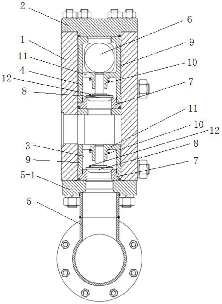
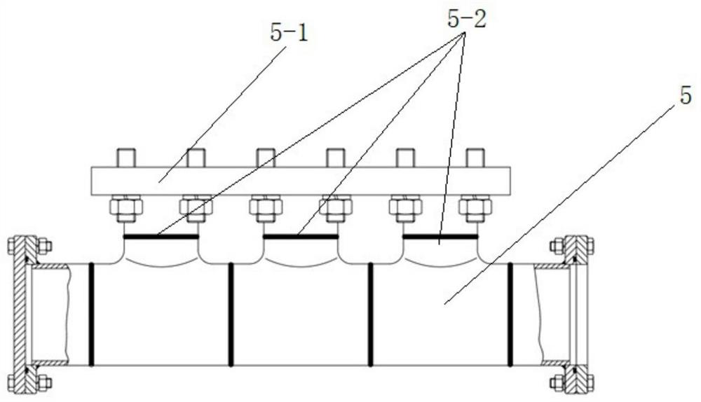
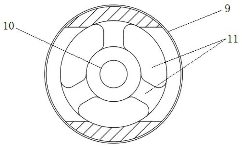
[0026] Such as Figure 1-4 As shown, a fluid end of a reciprocating plunger type polymer injection pump includes a liquid cylinder body 1, a liquid cylinder cover 2 is installed on the upper end of the liquid cylinder body 1, and several groups of valve groups are installed in the liquid cylinder body 1 mechanism, the valve group mechanism includes a vertically stacked suction valve 3 and a discharge valve 4, the lower end of the liquid cylinder body 1 is connected with a manifold-type suction main pipe 5, and the suction port of the suction valve 3 is connected...


PUM


Abstract

The invention discloses a reciprocating plunger type polymer injection pump fluid end. The fluid end comprises a hydraulic cylinder body, wherein a hydraulic cylinder cover is installed at the upper end of the hydraulic cylinder body, a plurality of groups of valve group mechanisms are installed in the hydraulic cylinder body, each valve group mechanism comprises a suction valve and a discharge valve which are vertically stacked, the lower end of the hydraulic cylinder body is connected with a manifold type suction header pipe, suction ports of the suction valves are all communicated with a suction header pipe, and the suction header pipe is connected with the lower end face of the hydraulic cylinder body through a connecting flange. A reciprocating plunger is arranged on one side of the hydraulic cylinder body in a penetrating manner, the reciprocating acting end of the plunger is located in a suction valve cavity of the suction valve, and discharge valve cavities of the discharge valves are communicated with one another to form a discharge flow channel. The discharge flow channel is of a large-small hole structure. According to the invention, the shear rate can be effectively reduced when a large-flow polymer is conveyed, so that the effectiveness of polymer oil displacement is ensured.

Description

technical field [0001] The invention relates to the technical field of polymer injection equipment for oil field tertiary oil recovery process, in particular to a fluid end of a reciprocating plunger type polymer injection pump. Background technique [0002] At present, with the continuous development and expansion of major oil fields and the continuous reduction of oil reservoirs, when the secondary oil recovery process cannot meet the oil recovery needs of the oil field, the tertiary oil recovery process is more and more widely used, among which the polymer injection process is currently effective. Oil flooding technology. The implementation of the polymer injection process will inevitably require the injection equipment - the polymer injection pump. The main difference between the polymer injection pump and other reciprocating pumps is the difference in the hydraulic end. The fluid end of the polymer injection pump not only requires stable flow and pressure operation, but...

Claims


Application Information

Patent Timeline
IPC IPC(8): F04B53/10F04B53/22F04B53/16E21B43/22
CPCE21B43/16F04B53/10F04B53/1002F04B53/16F04B53/162F04B53/22
Inventor 王超张碧莹李勇超李志亮冯菲娜谭国政侯磊王小杰唐春玲
Owner 宝鸡航天动力泵业有限公司
Why Eureka
Try Eureka