Fuel atomizing device and flame tube head structure having the same

A technology of flame tube head and fuel atomization, which is applied in the direction of combustion chamber, combustion method, combustion equipment, etc. It can solve the problems of fuel leakage from nozzles and stabilizers, failure to meet requirements, and carbon deposition on the head of the flame tube, etc., and achieve good results. Ignition and flameout performance, good atomization effect, and the effect of preventing the formation of carbon deposits on the head

Active Publication Date: 2022-08-09
AECC HUNAN AVIATION POWERPLANT RES INST
View PDF6 Cites 0 Cited by
  • Summary
  • Abstract
  • Description
  • Claims
  • Application Information

AI Technical Summary

Problems solved by technology

[0005] The present invention provides a fuel atomization device and the head structure of the flame tube to solve the problems of severe carbon deposition in the head of the flame tube, fuel leakage between the nozzle and the stabilizer, And technical problems that cannot meet the requirements of the high-temperature rise combustion chamber for the concentration field of the main combustion zone

Method used


Image

  • Fuel atomizing device and flame tube head structure having the same
  • Fuel atomizing device and flame tube head structure having the same
  • Fuel atomizing device and flame tube head structure having the same

Examples


Embodiment Construction

[0032] The embodiments of the present invention will be described in detail below with reference to the accompanying drawings, but the present invention can be implemented in many different ways as defined and covered below.

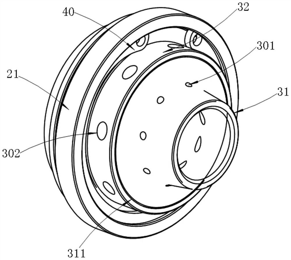
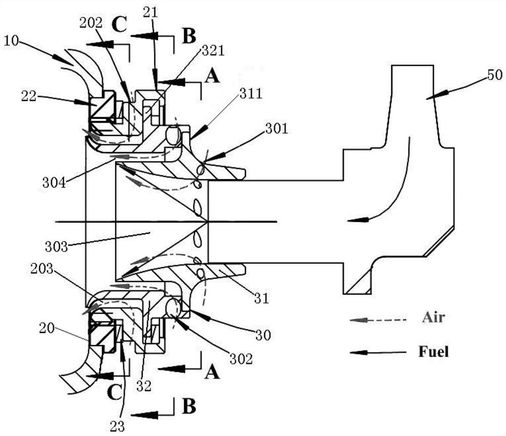
[0033] refer to figure 2 and image 3 , the preferred embodiment of the present invention provides a fuel atomization device, comprising: a vortexer fixing component 20 for fixing with the flame tube head 10, the vortexer fixing component 20 is a hollow cylinder with two ends connected, and the inner A vortex generator assembly 30 is arranged in the channel, a mounting limit ring 40 is installed between the vortex generator assembly 30 and the vortex generator fixing assembly 20, and the installation limit ring 40 is used to make the vortex generator assembly 30 float relative to the vortex generator fixing assembly 20. , the swirler assembly 30 is a hollow cylinder with two ends communicating, and a fuel nozzle 50 is inserted into the inflow end of th...


PUM


Abstract

The invention discloses a fuel atomization device and a flame tube head structure having the same, comprising: a vortexer fixing component, a vortexer component is arranged in an inner channel of the vortexer fixing component, and a vortexer component is arranged between the vortexer component and the vortexer fixing component An installation limit ring is installed, and the installation limit ring is used for floating installation of the vortex generator assembly relative to the vortex generator fixing assembly, and a fuel nozzle is inserted into the inflow end of the channel in the vortex generator assembly. A first swirl hole group is arranged on the wall surface of the vortexer assembly, and the first swirl hole group is used to introduce the external airflow into the inner channel of the vortexer assembly, and form a high-speed swirling airflow that rotates at a high speed along the circumferential direction, and then The high-speed rotating airflow cuts the fuel injected by the fuel nozzle into tiny oil droplets. A second swirl hole group is arranged in the wall surface of the vortex device fixing assembly, and the second swirl hole group is used to introduce the external air flow into the channel of the flame tube head, and form a circumferential rotation and close to the flame tube head. The rotating covering gas film flowing on the inner wall surface.

Description

technical field [0001] The present invention relates to the technical field of gas turbine engine combustion chambers, and in particular, to a fuel atomization device. In addition, the invention also relates to a flame tube head structure with the fuel atomizing device. Background technique [0002] The fuel atomization device is an important component of the combustion chamber of the gas turbine engine. Each turbo power machine has at least one nozzle to provide fuel, and under the action of the atomization device, an oil mist field is formed to burn, and the working performance of the fuel atomization device is good or bad. It directly affects the ignition performance, combustion performance and pollution emission performance of the combustion chamber. [0003] figure 1 It is a fuel atomization device currently in use. The fuel atomization device consists of a nozzle and a stabilizer. The stabilizer and the flame tube are fixed by welding. The stabilizer is a bowl-shaped...

Claims


Application Information

Patent Timeline
Patent Type & Authority Patents(China)
IPC IPC(8): F23R3/30F23R3/12F23R3/42
CPCF23R3/30F23R3/12F23R3/42
Inventor 王帅沈荻杨浩刘逸博李炜彭畅新王梅娟林志勇尹美芝
Owner AECC HUNAN AVIATION POWERPLANT RES INST
Why Eureka
Try Eureka