
Surface chip mounting process

A chip mounting and process technology, applied in the field of surface chip mounting technology, can solve problems such as desoldering, and achieve the effect of reducing desoldering problems

Pending Publication Date: 2021-07-23
浙江集迈科微电子有限公司
View PDF0 Cites 0 Cited by
  • Summary
  • Abstract
  • Description
  • Claims
  • Application Information

AI Technical Summary

Problems solved by technology

[0003] However, with the application in some special areas, especially the popularization of artificial wearable products, more and more electronic modules have changed from flat to curved, which requires the welding technology of chips to change from flat to curved, especially when the base When the surface is curved before soldering, only a part of the BGA solder balls with a flat chip surface can be soldered to the pad, and other areas will be desoldered due to insufficient distance

Method used


Image

  • Surface chip mounting process
  • Surface chip mounting process
  • Surface chip mounting process

Examples


Embodiment Construction

[0019] In order to make the object, technical solution and advantages of the present invention clearer, the present invention will be further described in detail below in conjunction with the accompanying drawings and embodiments. It should be understood that the specific embodiments described here are only used to explain the present invention, not to limit the present invention.

[0020] Furthermore, repeated reference numerals or designations may be used in different embodiments. These repetitions are only for the purpose of simply and clearly describing the present invention, and do not represent any relationship between the different embodiments and / or structures discussed.

[0021] The reference numerals related to the steps mentioned in the various embodiments of the present invention are only for the convenience of description, and there is no actual sequence connection. Different steps in each specific implementation manner can be combined in different sequences to a...


PUM


Abstract

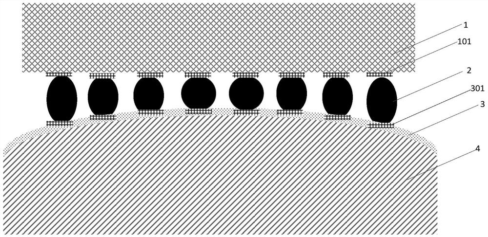
The invention provides a surface chip mounting process. The surface chip mounting process comprises the following steps of: S1, providing a wafer, preparing a first bonding pad on the surface of the wafer, planting a solder ball with the same height on the first bonding pad located on the surface of the wafer, conducting welding to obtain a wafer with a surface planted with the solder ball, and then cutting the wafer to obtain a chip having the solder ball with the same height; S2, providing a flexible film and manufacturing a second bonding pad on the surface of the flexible film, wherein an isolation layer is arranged between the second bonding pad and the flexible film; S3, mounting chip with the solder ball on the surface of the flexible film in a surface mounting mode, welding the solder ball on the chip to the second bonding pad on the surface of the flexible film through reflow soldering, and combining the flexible film with a mold in the reflow soldering process so as to obtain solder ball distribution identical with the surface morphology of the mold; and S4, separating the solder ball together with the second bonding pad from the flexible film to obtain a chip with surface solder ball height matched with the curved surface of a base. According to the invention, the problem of sealing-off is reduced.

Description

technical field [0001] The invention relates to the technical field of semiconductors, in particular to a surface chip mounting process. Background technique [0002] The planar chip technology can interconnect the chip with BGA solder balls with the base (such as PCB or substrate) with pads on the surface. This technology requires the plane of BGA solder balls to be in the same plane, and the difference in height is small. , it is also required that the plane of the base pad is also in the same planarity. [0003] However, with the application in some special areas, especially the popularization of artificial wearable products, more and more electronic modules have changed from flat to curved, which requires the welding technology of chips to change from flat to curved, especially when the base When the surface is curved before soldering, only a part of the BGA solder balls with a flat chip surface can be soldered to the pad, and other areas will be desoldered due to insuf...

Claims


Application Information

Patent Timeline
IPC IPC(8): H01L21/48
CPCH01L21/4814H01L24/11H01L2224/1111
Inventor 冯光建黄雷郭西顾毛毛高群
Owner 浙江集迈科微电子有限公司
Learn More