
Pollutant collection and treatment equipment for oncology department nursing

A technology for processing equipment and pollutants, which is applied in the field of pollutant collection and treatment equipment for oncology nursing, which can solve the problems of personal safety, small size of metal needles, and unrealistic problems, so as to achieve safe working process, avoid sticking phenomenon, and ensure safety Effect

Active Publication Date: 2021-07-27
ZHENJIANG NO 1 PEOPLES HOSPITAL
View PDF5 Cites 0 Cited by
  • Summary
  • Abstract
  • Description
  • Claims
  • Application Information

AI Technical Summary

Problems solved by technology

[0002] In the process of nursing in the oncology department, due to the need to use more consumables and drugs during nursing, a certain amount of medical waste will be generated, and the composition of the medical waste is relatively complex, including metal needles, medical PVC materials, glass waste and human body. Body fluid or medical liquid cleaning solution, etc., are more troublesome in the process of subsequent treatment
[0003] Due to the many types of doping in medical waste, it is unrealistic to treat them in a unified way during collection and treatment. If safety treatment is not carried out during the process, it is easy to cause the medical staff who deal with the garbage to be stabbed, resulting in personal safety, and may also cause medical accidents such as cross-infection
In the prior art, many needles are frictionally passivated. However, due to the small size of the metal needle, it is difficult to clamp and fix the metal needle conveniently during the friction passivation process, so that the subsequent passivation of the metal needle cause some trouble

Method used


Image

  • Pollutant collection and treatment equipment for oncology department nursing
  • Pollutant collection and treatment equipment for oncology department nursing
  • Pollutant collection and treatment equipment for oncology department nursing

Examples


Embodiment 1

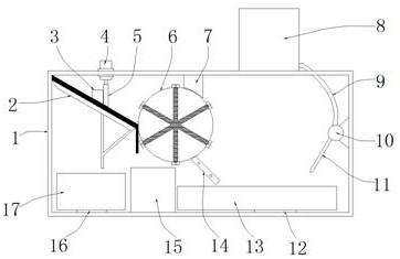
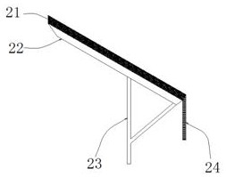
[0034] refer to Figure 1-2 with Figure 9 , a pollutant collection and treatment device for oncology care, including a treatment shell 1, an opening (not shown in the figure) is provided on the top side of the treatment shell 1, and a slope is fixedly installed directly below the opening. The draining device 2 provided, the draining device 2 includes a draining plate 21, the draining plate 21 is evenly provided with draining holes, and the top of the processing shell 1 is vertically provided with a push rod that runs through the top of the processing shell 1 on one side of the opening Motor 4, the output shaft of push rod motor 4 is vertically downward, and its output shaft is fixedly connected with the baffle plate 5 that fits with the top of draining device 2, so that the pollutants produced in the nursing process of the oncology department can be discharged on the draining plate 21. Cooperate with the function of the baffle plate 5 to drain water when standing still, so t...

Embodiment 2

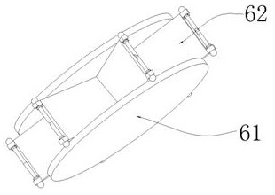
[0038] refer to figure 1 , Figure 3-8, one side of the processing housing 1 is fixedly installed with a servo motor 18 whose output shaft points to the horizontal direction, the first pressure sensor 16 is electrically connected to the servo motor 18, and the output shaft of the servo motor 18 penetrates and extends to the inside of the processing housing 1, And concentrically connected with a screening mechanism 6, the screening mechanism 6 is attached to the bottom of the draining device 2, that is, after the working steps of the first embodiment are completed, the first pressure sensor 16 controls the servo motor 18 to work, thereby driving its electric The connected screening mechanism 6 rotates so that the falling pollutants can be collected. The screening mechanism 6 has two sets of rotating plates 61 arranged in parallel, and several groups of adsorption devices 62 are fixedly installed in an annular array between the rotating plates 61 , the adsorption device 62 incl...

Embodiment 3

[0043] refer to figure 1 , the inside of the processing housing 1 is provided with a needle collection box 13 below the lower end of the power-off part 14, and the top of the processing housing 1 is fixedly installed on the side away from the opening. The storage box 8 is equipped with a Cured resin materials, etc., one side of the lower part of the storage box 8 is connected with a conduit 9 that runs through and extends to the inside of the processing shell 1, and one end of the conduit 9 is connected with a high-viscosity pump 10 that is fixedly connected to the inner wall of the processing shell 1, and the needles are collected. The bottom end of the box 13 is provided with a second pressure sensor 12, and the second pressure sensor 12 is electrically connected with the high viscosity pump 10, and the output end of the high viscosity pump 10 is connected with a nozzle 11 pointing to the inside of the needle collection box 13, when the needle collects When the quality of th...


PUM


Abstract

The invention relates to the technical field of medical waste treatment, in particular to pollutant collection and treatment equipment for oncology department nursing. The pollutant collection and treatment equipment comprises a treatment shell, wherein one side of the top end of the treatment shell is provided with an opening, an inclined draining device is fixedly mounted right below the opening in the treatment shell, and a water storage tank is fixedly mounted right below the draining device in the treatment shell. According to the equipment, solid-liquid separation can be effectively carried out on pollutants generated in the nursing process of the oncology department, and convenience is provided for subsequent treatment of medical pollutants; subsequent solid dirt can be effectively separated, and metal needles doped in the solid dirt can be effectively stripped out, so the safety of medical staff and sanitary staff is guaranteed, and the phenomenon of pricking people and even medical accidents are avoided; and in the process of treating metal needle heads, the needle heads are passivated on the whole, a working process is safer, and subsequent treatment personnel can conveniently operate.

Description

technical field [0001] The invention relates to the technical field of medical waste treatment, in particular to a pollutant collection and treatment equipment for oncology care. Background technique [0002] In the process of nursing in the oncology department, due to the need to use more consumables and drugs during nursing, a certain amount of medical waste will be generated, and the composition of the medical waste is relatively complex, including metal needles, medical PVC materials, glass waste and human body. Body fluids or medical liquid cleaning fluids are more troublesome in the process of subsequent treatment. [0003] Due to the many types of doping in medical waste, it is unrealistic to treat them in a unified way during collection and treatment. If safety treatment is not carried out in the process of garbage disposal, it is easy to cause medical staff who dispose of garbage to be stabbed, resulting in personal safety, and may also cause medical accidents such...

Claims


Application Information

Patent Timeline
Patent Type & Authority Applications(China)
IPC IPC(8): B01D36/00
CPCB01D36/00
Inventor 焦丽萍庄利梅赵萍蒋芳张绘慧
Owner ZHENJIANG NO 1 PEOPLES HOSPITAL
Learn More