
Lifting type cleaning mechanism for coated optical parts

A technology for cleaning mechanisms and parts, which is applied to cleaning methods using liquids, dryers, chemical instruments and methods, etc., which can solve the problems of reduced cleaning quality, easy water pollution, and inability to rinse in time, and achieve cleaning efficiency and The effect of improving quality, improving equipment efficiency and better water removal effect

Inactive Publication Date: 2021-07-27
扬州辰亚光学科技有限公司
View PDF14 Cites 0 Cited by
  • Summary
  • Abstract
  • Description
  • Claims
  • Application Information

AI Technical Summary

Problems solved by technology

[0003] When realizing this technical solution, there are at least the following defects: for example 1. the publication number is (CN110586563A) a kind of lifting type cleaning mechanism used for optical parts after coating, which is used for lifting type cleaning after optical parts coating The mechanism can quickly and stably clean and dry, and improve work efficiency, but the structure can only perform a single cleaning of the parts, and it cannot be rinsed in time after cleaning, resulting in poor cleaning quality, and more cleaning liquid adheres to the surface of the parts after cleaning , so that the air-drying speed is greatly reduced, which affects the efficiency and increases the cost of equipment use;
[0004] 2. A cleaning and drying equipment for optical parts of electronic equipment with the publication number (CN212310244U). The water pipe and the nozzle spray the cleaning water on the parts, and start the rotating motor to drive the cleaning cylinder to rotate, so that the parts can be cleaned. When one side is cleaned, turn the parts over and the other side is up, and then repeat the operation to complete the zero alignment. For parts cleaning, when the cleaning is completed, the cleaning cylinder is rotated at high speed to dry the water on the cleaning cylinder, and then the blower is started to dry the parts, which further saves manual cleaning and improves work efficiency. However, when the device is used, it uses The cleaning bucket is located on the component and rotates to complete the cleaning, which is easy to cause wear to the coating layer. At the same time, it is impossible to clean both sides at the same time, the cleaning efficiency and quality are greatly reduced, and manual operation is required during operation, which is cumbersome and inconvenient;
[0005] 3. Publication No. (CN204699985U) is a lift-type cleaning mechanism for optical components after coating. The mechanism uses a cleaning water tank to cooperate with the lifting mechanism. Through the continuous up and down reciprocating motion of the lifting mechanism, the optical components and clean water The solution in the water tank fully reacts to achieve the cleaning effect, and drains it after cleaning to meet the process requirements of continuous production of products. However, the device needs to be drained naturally when it is used, and the drying speed is slow, which seriously affects the clearing efficiency. It is carried out in a group of cleaning tanks, the water in the cleaning tank is easily polluted, and the cleaning quality will gradually decline;

Method used


Image

  • Lifting type cleaning mechanism for coated optical parts
  • Lifting type cleaning mechanism for coated optical parts
  • Lifting type cleaning mechanism for coated optical parts

Examples


Embodiment Construction

[0032] In order to make the technical means, creative features, goals and effects achieved by the present invention easy to understand, the present invention will be further described below in conjunction with specific embodiments.

[0033] In describing the present invention, it should be understood that the terms "upper", "lower", "front", "rear", "left", "right", "top", "bottom", "inner", " The orientation or positional relationship indicated by "outside", etc. is based on the orientation or positional relationship shown in the drawings, and is only for the convenience of describing the present invention and simplifying the description, rather than indicating or implying that the referred device or element must have a specific orientation, so as to Specific orientation configurations and operations, therefore, are not to be construed as limitations on the invention.

[0034] In the description of the present invention, it should be noted that, unless otherwise specified and...


PUM


Abstract

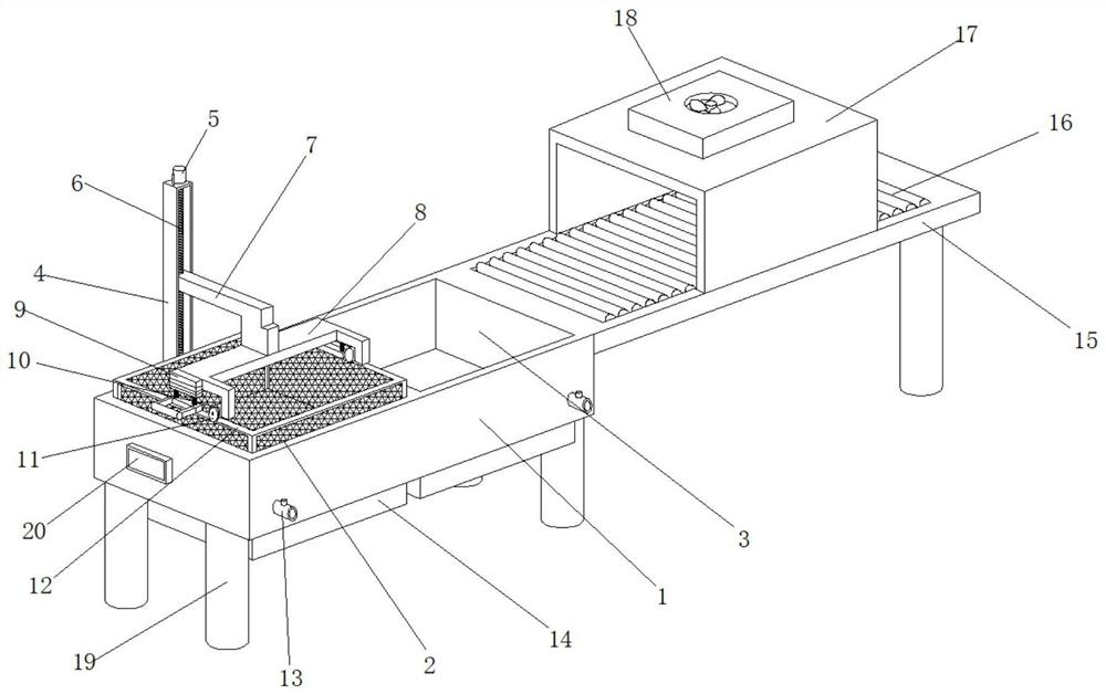
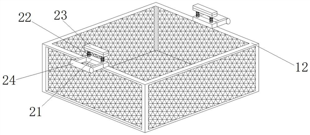
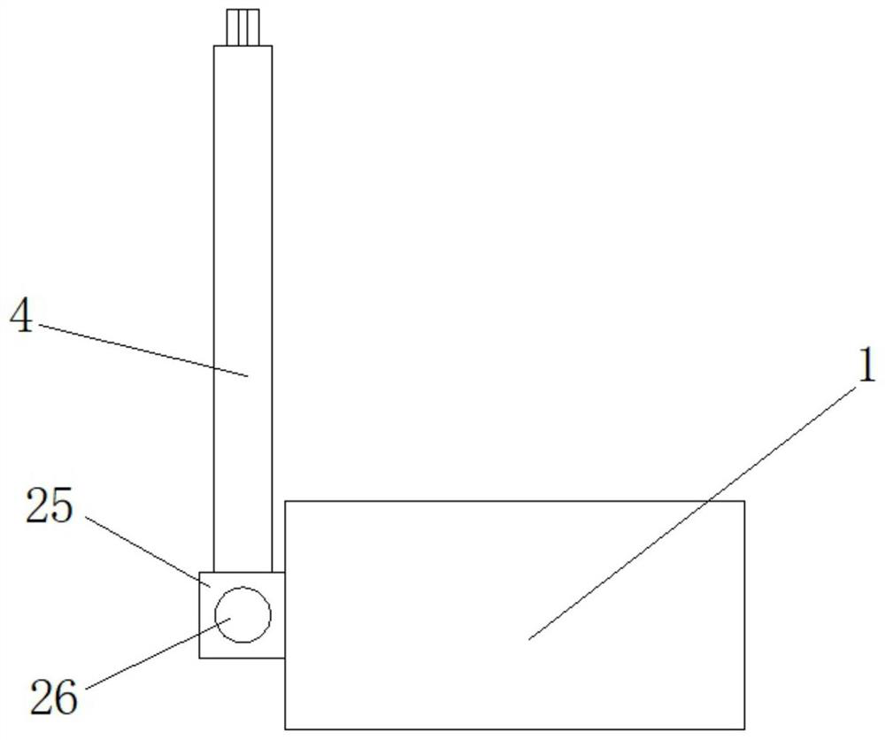
The invention relates to the technical field of cleaning of optical parts, and discloses a lifting type cleaning mechanism for coated optical parts. The lifting type cleaning mechanism comprises a cleaning box, a transmission table and a cleaning net basket, wherein cleaning pool is arranged on the left side of the interior of the cleaning box, and a rinsing pool is arranged on the right side of the interior of the cleaning box; a rail A is arranged on the rear side of the cleaning box, and a sliding block is movably arranged in the rail A; a screw hole A is formed in the middle of the sliding block in a penetrating mode; and a screw A is transversely arranged in the rail A. Automatic integrated work of cleaning, rinsing and air drying can be achieved through the cleaning pool, the rinsing pool, an air drying box and all driving structures, and the cleaning efficiency and quality are greatly improved. The cleaning net basket can be driven to vibrate through an eccentric wheel and a spring column after cleaning and rinsing, and therefore attached water can be shaken out, and pollution of cleaning water to rinsing water is avoided. The amount of water attached to the surfaces of the parts can be reduced after rinsing, so that follow-up air drying is faster and more efficient, and the quality is improved.

Description

technical field [0001] The invention relates to the technical field of optical parts cleaning, in particular to a lifting type cleaning mechanism for optical parts after coating. Background technique [0002] At present, optical parts, also known as optical elements, are the basic components of the optical system. Most of the optical parts play an imaging role, such as lenses, prisms, mirrors, etc. Optical parts play the role of imaging, such as lenses, prisms, mirrors, etc. In addition, there are some parts that play special roles in the optical system, such as reticles, filters, gratings for optical fiber parts, etc., holographic lenses, Gradient refractive index lenses, binary optical elements, etc. are new optical parts that have appeared in the past ten or twenty years. These optical parts often need to be coated after production to prevent wear and tear and have a better protective effect. After coating, they need to be coated. Cleaning is carried out to remove the di...

Claims


Application Information

Patent Timeline
Patent Type & Authority Applications(China)
IPC IPC(8): B08B3/12B08B3/10B08B13/00F26B21/00
CPCB08B3/12B08B3/10B08B13/00F26B21/001
Inventor 戚志洋
Owner 扬州辰亚光学科技有限公司
Learn More