Internal and external cyclone reverse shunting-type air dedusting method and device

An air dust removal and split flow technology, which is applied in the field of air purification, can solve the problems of limited use range, high space requirements for the use site, and high noise.

Pending Publication Date: 2021-07-30
张昌锐
View PDF1 Cites 2 Cited by
  • Summary
  • Abstract
  • Description
  • Claims
  • Application Information

AI Technical Summary

Problems solved by technology

Limited by the structural design of the cyclone dust collector itself, this type of dust removal device can basically only separate non-sticky, non-fibrous dry dust with a particle size of more than 0.5 microns, and purify the dusty air with a particle size of less than 0.5 microns The effect is not ideal, and the scope of use is severely limited
Moreover, the overall structure of this type of dust removal device is relatively complicated, and the cyclone dust collector is usually designed to be taller and larger, and it is necessary to connect an additional circulating air duct to the cyclone dust collector to purify the dust with a small amount of dust separated from the cyclone dust collector. The air is recirculated and purified, resulting in a large overall volume and a large footprint of the device, which requires a high space for the use site, and high energy consumption, high noise, and high manufacturing and use costs during actual work.

Method used


Image

  • Internal and external cyclone reverse shunting-type air dedusting method and device
  • Internal and external cyclone reverse shunting-type air dedusting method and device
  • Internal and external cyclone reverse shunting-type air dedusting method and device

Examples


Embodiment Construction

[0039] The present invention will be further described below with reference to the accompanying drawings and preferred specific embodiments of the present invention.

[0040] refer to Figure 1 to Figure 2 As shown in the present invention:

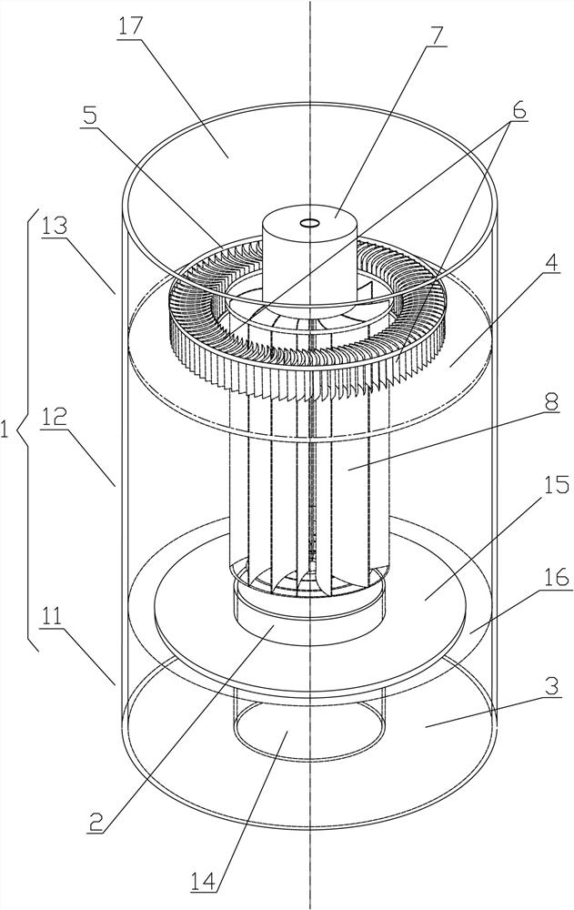
[0041] An inner and outer cyclone reverse split-flow air dust removal device, comprising a shell 1 with a cylindrical structure as a whole, the cylindrical shell 1 can be divided into interconnected ones in order from bottom to top in the axial direction of the cylindrical shell 1 , the air inlet dust collecting section 11 located in the lower part of the shell 1 , the cyclone reverse splitting section 12 located in the middle of the shell 1 , and the exhaust section 13 located in the upper part of the shell 1 .

[0042] Specifically, the air intake and dust collection section 11 includes an air intake duct 2 axially disposed at the middle of the bottom surface of the housing 1 and a dust collection box 3 disposed outside the air intake ...


PUM


Abstract

The invention relates to the technical field of air dust removal, in particular to an internal and external cyclone reverse shunting-type air dedusting method and device, and solves the technical defects that existing cyclone centrifugal dust removal devices are complex in structure and large in size. According to the technical scheme, a shell is divided into an air inlet dust collection section, a cyclone reverse shunting section and an air exhaust section, the air inlet dust collection section comprises an air inlet barrel and a dust collection box, and the cyclone reverse shunting section comprises a packing ring, a flow deflector, a fixed plate, a driving shaft and a centrifugal impeller. The device has the beneficial effects that: the centrifugal impeller drives dust-containing air to move to form rotationally-rising inner cyclone, particle impurities in the dust-containing air radially settle under the action of centrifugal force and gravity to form external airflow, clean air rises to the upper end of the centrifugal impeller and enters the exhaust section through a radial air inlet channel and a radial air outlet channel, a small amount of clean air is shunted and returned under the action of the flow deflector and drives external airflow to rotate and descend to form outer cyclone, most of the impurities settle in the dust collection box, a small amount of the impurities converges into inner cyclone, and the device is good in dust removal effect, simple in structure and small in size.

Description

technical field [0001] The invention relates to the technical field of air purification, and more particularly to an inner and outer cyclone reverse split air dedusting method and a dedusting device using the method. Background technique [0002] Air dust removal refers to the use of centrifugal separation, gravity separation, filtration separation, electrostatic adsorption separation or washing separation and other methods to separate inhalable particulate impurities from dust-laden air with the help of a dust removal device corresponding to the dust removal method, thereby producing purified air. Wide range of applications, widely used in ventilation and air conditioning systems, air purification systems, industrial dust removal systems, oil fume purification systems, welding fume purification systems, paint mist purification systems in painting workshops and other fields, with extremely high environmental, economic and social value . [0003] Centrifugal separation dust ...

Claims


Application Information

Patent Timeline
IPC IPC(8): B01D45/14B01D45/18B01D45/16
CPCB01D45/14B01D45/16B01D45/18
Inventor 张昌锐
Owner 张昌锐
Why Eureka
Try Eureka