Petroleum catalytic cracking reaction kettle

A catalytic cracking and reactor technology, applied in catalytic cracking, cracking, petroleum industry, etc., can solve problems such as single function, elongated process, and low work efficiency

Inactive Publication Date: 2021-07-30
赵晓辉
View PDF0 Cites 2 Cited by
  • Summary
  • Abstract
  • Description
  • Claims
  • Application Information

AI Technical Summary

Problems solved by technology

[0005] In view of the above technical problems, the present invention provides a petroleum catalytic cracking reactor, which can effectively solve the problem that the current petroleum catalytic cracking reactor has simple structure and single function, and can only provide reaction space for petroleum catalytic cracking, and the addition of catalyst and The heating of the oil must be completed by other corresponding equipment, which makes the process lengthened and the work efficiency is low

Method used


Image

  • Petroleum catalytic cracking reaction kettle
  • Petroleum catalytic cracking reaction kettle
  • Petroleum catalytic cracking reaction kettle

Examples


Embodiment 1

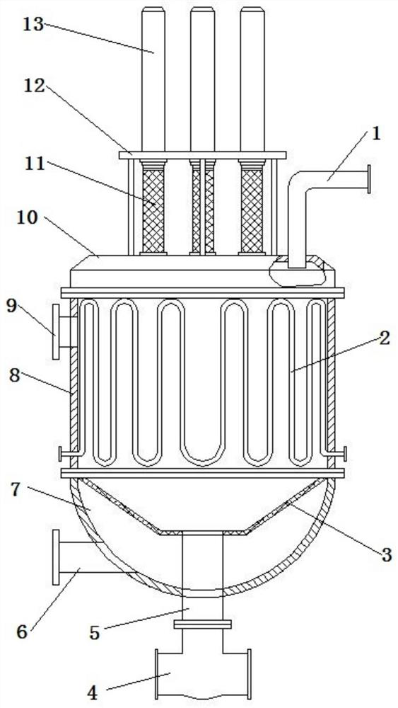
[0026] Such as figure 1 Shown, a kind of petroleum catalytic cracking reactor comprises reactor body, and reactor body comprises cylinder body 8, and cylinder body 8 top is provided with top cover 10, and cylinder body 8 bottom is provided with bottom shell 7, cylinder body 8 and top cover 10 and The bottom shell 7 is connected by a flange. The top cover 10 is provided with a catalyst adding mechanism and an oil-gas conduit 1. The oil-gas conduit 1 is connected to the fractionation equipment. The cylinder body 8 is provided with a petroleum inlet 9 and a heating mechanism. The bottom shell 7 An oil discharge port 6 is arranged on the top, and an oil residue separation mechanism is arranged in the bottom shell 7 , and the slag discharge part of the oil residue separation mechanism is connected with the slag discharge assembly arranged at the bottom of the bottom casing 7 .

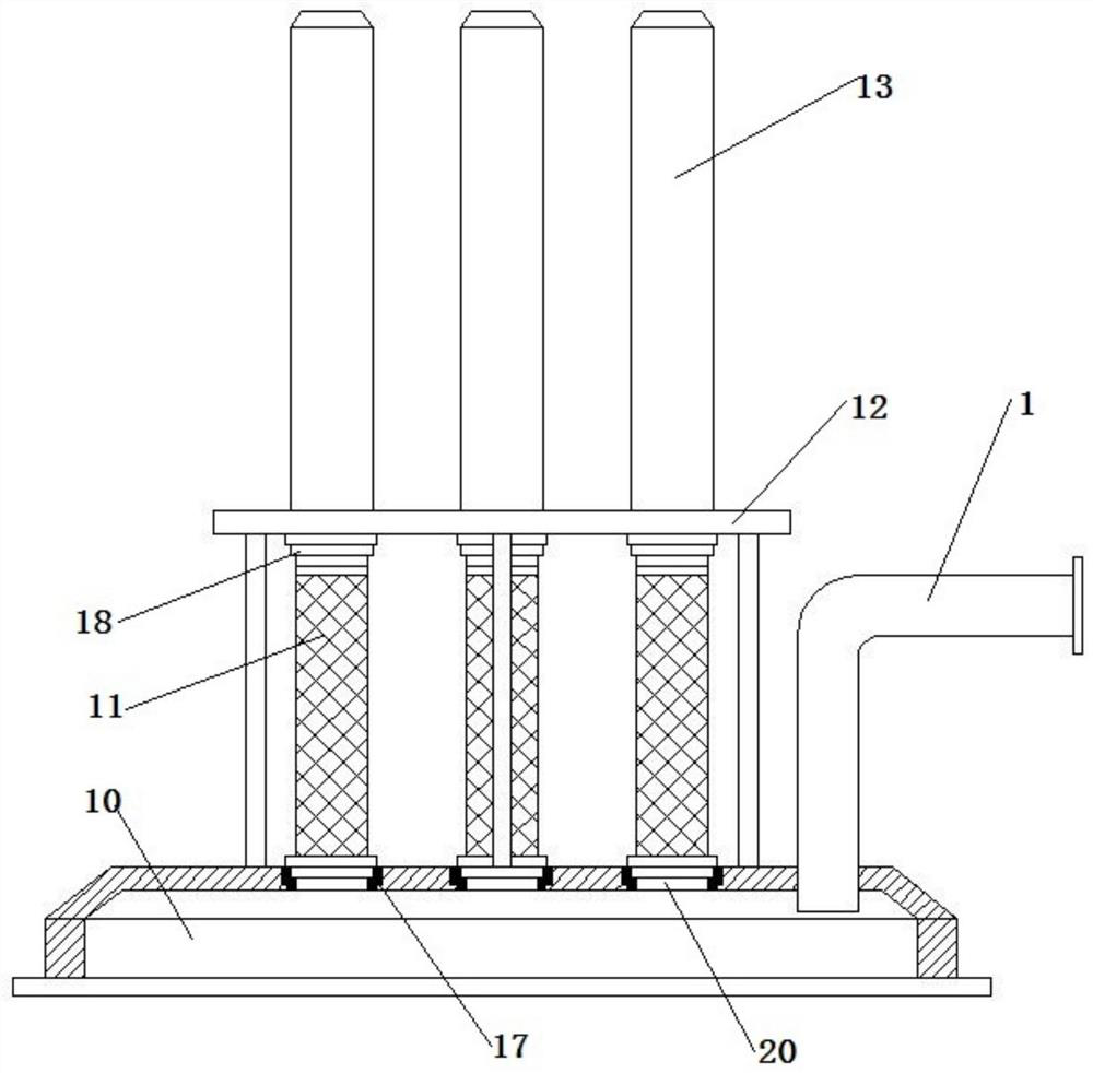
[0027] Such as figure 1 , image 3 and Figure 4 As shown, the catalyst adding mechanism includes a s...

Embodiment 2

[0034] Such as Figure 5 , Figure 6 As shown, the catalyst adding mechanism comprises a support frame 12, a screw rod 23 and a sliding column 24 are vertically arranged in the support frame 12, a bearing plate 25 is horizontally arranged in the support frame 12, the carrying plate 25 is threadedly connected with the screw rod 23, and the carrying plate 25 is connected with the sliding column 24 Sliding connection, the lower part of the bearing plate 25 is provided with several material net cylinders 11, the upper end of the material net cylinder 11 is threadedly connected with the bearing plate 25, the lower end of the material net cylinder 11 corresponds to the inlet 20 arranged on the top cover 10, and the upper part of the support frame 12 is set The power source 22 is fitted with a turbine 26 on the rotating shaft of the power source 22. The turbine 26 and the screw rod 23 are engaged with each other. Rib 21.

[0035] Such as Figure 6 As shown, a sliding bar is provid...

Embodiment 3

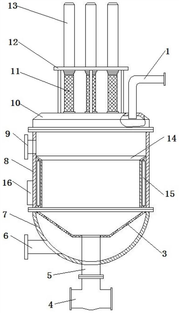
[0039] Such as figure 2 As shown, the heating mechanism includes a heating shell 14 arranged on the inner wall of the cylinder body 8 , a heating pipe 15 is arranged in the heating casing 14 , and the heating pipe 15 is connected to a power supply box 16 arranged on the outer wall of the cylinder body 8 .

[0040] When the present embodiment is in operation, the heating tube 15 is powered and generates heat, and the heating tube 15 transfers heat to the oil in the kettle body through the heating shell 14 to heat the oil.

[0041] Other structures and methods of use are consistent with Example 1.


PUM


Abstract

The invention discloses a petroleum catalytic cracking reaction kettle which comprises a reaction kettle body, the reaction kettle body comprises a barrel, a top cover is arranged on the upper portion of the barrel, a bottom shell is arranged on the lower portion of the barrel, a catalyst adding mechanism and an oil gas guide pipe are arranged on the top cover, the oil gas guide pipe is connected with fractionation equipment, a petroleum feeding hole and a heating mechanism are arranged on the barrel body, a petroleum discharging hole is formed in the bottom shell, an oil residue separating mechanism is arranged in the bottom shell, and a residue discharging part of the oil residue separating mechanism is connected with a residue discharging assembly arranged at the bottom of the bottom shell in a matched mode. An existing petroleum catalytic cracking reaction kettle is simple in structure and single in function, only a reaction space is provided for petroleum catalytic cracking, catalyst adding and oil heating must be completed through other corresponding equipment, the technological process is prolonged, and the working efficiency is low.With the petroleum catalytic cracking reaction kettle adopted, the above problems can be solved.

Description

technical field [0001] The invention relates to the technical field of petroleum catalytic cracking equipment, in particular to a petroleum catalytic cracking reaction kettle. Background technique [0002] Petroleum is a viscous, dark brown liquid known as the "blood of industry". There are oil reserves in parts of the upper crust. The main component is a mixture of various alkanes, naphthenes and aromatic hydrocarbons. It is one of the main objects of geological exploration. [0003] The oil-forming mechanism of petroleum has two theories of biosedimentary oil and petrochemical oil. The former is more widely accepted. It is believed that oil is formed by organisms in ancient oceans or lakes after a long evolution. It belongs to biosedimentary oil and is non-renewable. It is believed that petroleum is generated from the carbon in the earth's crust itself, has nothing to do with biology, and is renewable. Petroleum is mainly used as fuel oil and gasoline, and is also a ra...

Claims


Application Information

Patent Timeline
IPC IPC(8): B01J8/06C10G11/00
CPCB01J8/06C10G11/00
Inventor 赵晓辉
Owner 赵晓辉
Why Eureka
Try Eureka