
Robot joint speed reducer based on nutation speed reduction and friction transmission and design method

A technology of robot joints and friction transmission, which is applied in the direction of friction transmission devices, transmission boxes, mechanical equipment, etc., can solve the problems of complex overall structure, limited service life, difficult assembly and maintenance, etc., and achieve high transmission accuracy, high positioning accuracy, and structure simple effect

Pending Publication Date: 2021-07-30
赣州精诚机械制造有限公司
View PDF0 Cites 2 Cited by
  • Summary
  • Abstract
  • Description
  • Claims
  • Application Information

AI Technical Summary

Problems solved by technology

[0003] However, the existing joint reducers have defects such as complex overall structure, difficult assembly and maintenance, and limited service life by materials.

Method used


Image

  • Robot joint speed reducer based on nutation speed reduction and friction transmission and design method
  • Robot joint speed reducer based on nutation speed reduction and friction transmission and design method

Examples


Embodiment 1

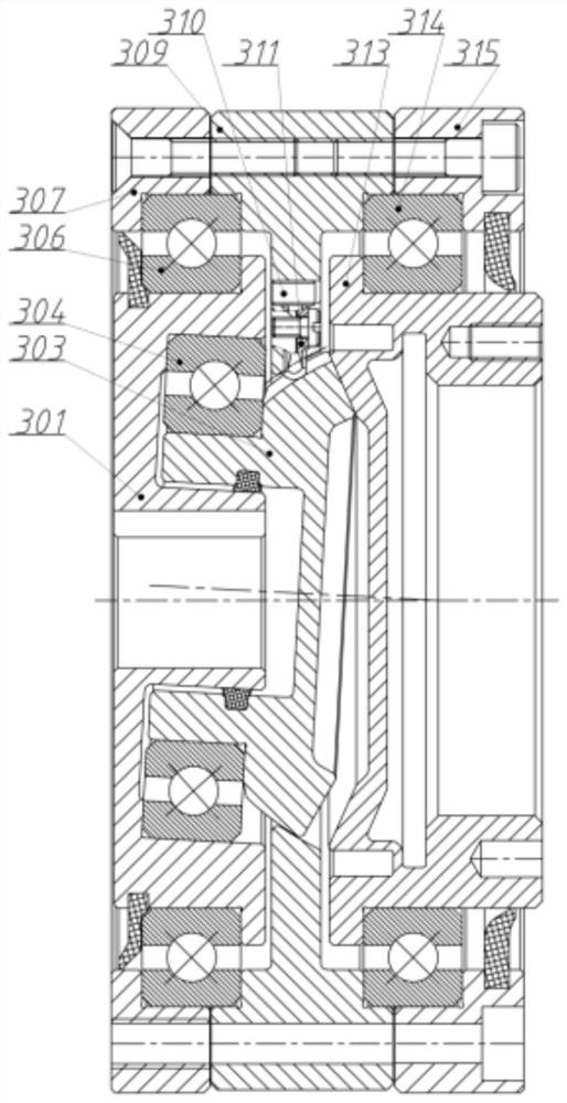
[0033] Such as figure 1 As shown, the present invention provides a technical solution: a robot joint reducer based on nutation deceleration and friction transmission, which is characterized in that it includes:

[0034] The shell, the shell is composed of the bearing base 309, the upper positioning ring 315, and the lower positioning ring 307. The shell is used as the installation reference of the reducer to position and install the reducer body. There are positioning pins 310 and small splints 311,

[0035] A nutating wheel seat 301, the nutating wheel seat 301 is installed on the lower positioning ring 307, and a nutating wheel 303 is installed on the nutating wheel seat 301;

[0036] It also includes an output flange 313 installed on the upper positioning ring 315 .

[0037] A pair of thin-walled four-point contact ball bearings or crossed roller bearings are installed in the housing, which are used as the rotation reference of the nutating wheel base 301 and the output f...

Embodiment 2

[0044] exist figure 1 The specific embodiment shown is a flat cylindrical precision reducer for the end joints of a small 6-joint manipulator, with a design reduction ratio of 40:1, a design power capacity of 100W, and a design maximum output torque of 20N·m.

[0045] Since the transmission parts of the reducer rely on rolling friction as the driving force, in order to ensure the life and performance of the core parts of the reducer, bearing steel or high manganese spring steel is generally used as the material of the parts. Under the condition of non-lubricated static friction, the friction coefficient between steel and steel is calculated as 0.15. The diameter of the large end of the inner cone surface of the primary selection output flange is 41mm, and the required static friction force is 1kN. According to the reduction ratio, the cone surface of the nutating wheel is larger The end diameter is 40mm.

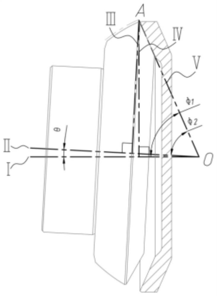
[0046] The primary nutation angle θ = 3°, and the cone angle of the nu...


PUM


Abstract

The invention discloses a robot joint speed reducer based on nutation speed reduction and friction transmission and a design method. The robot joint speed reducer comprises a shell jointly composed of a bearing base, an upper positioning ring and a lower positioning ring, a nutation wheel base installed on the lower positioning ring and a nutation wheel installed on the nutation wheel base. The robot joint speed reducer further comprises an output flange, a positioning needle and a small clamping plate. The output flange is installed on the upper positioning ring, and the positioning needle and the small clamping plate are installed on the bearing base. Under the limiting effect of the positioning needle and the driving of the rotary motion of the nutation wheel base, the nutation wheel generates nutation motion, the output flange is pushed to rotate under the effect of friction force, and decelerating motion is generated. The robot joint speed reducer based on nutation speed reduction and friction transmission and the design method have the advantages of reasonable torque load, large transmission speed ratio, high transmission precision, stable transmission, reverse self-locking, simple and compact structure and the like.

Description

technical field [0001] The invention relates to the technical field of robot joint reducers, in particular to a robot joint reducer based on nutation reduction and friction transmission and a design method. Background technique [0002] With the process of industrialization and the gradual development of automation and unmanned chemical factories, the application of industrial robots in various fields is expanding day by day, but there is still a certain gap between the key parts industry of robots in my country and the developed countries in the world. Among the components of industrial robots, the joint reducer is the most critical component in the body of the joint industrial robot, which has the function of ensuring the positioning accuracy and service life of the industrial robot. [0003] However, the existing joint reducers have defects such as complex overall structure, difficult assembly and maintenance, and limited service life by materials. Contents of the inven...

Claims


Application Information

Patent Timeline
Patent Type & Authority Applications(China)
IPC IPC(8): B25J17/02B25J19/00F16H13/06F16H57/02F16H57/021F16H57/023F16H57/08
CPCB25J17/02B25J19/007F16H13/06F16H57/02F16H57/021F16H57/023F16H57/08F16H2057/0087F16H2057/02069F16H2057/02095
Inventor 刘昊刘赣伟
Owner 赣州精诚机械制造有限公司
Learn More