
Improved large ozone generator

An ozone generator and generator technology, which is applied in ozone preparation, oxidized water/sewage treatment, etc., can solve the problems of reducing the use effect of large ozone generators, affecting the quality and effect of ozone, and affecting ozone ejection, so as to improve heat dissipation. effect, improve heat dissipation effect, improve quality effect

Pending Publication Date: 2021-07-30
宿州龙润生物科技有限公司
View PDF0 Cites 0 Cited by
  • Summary
  • Abstract
  • Description
  • Claims
  • Application Information

AI Technical Summary

Problems solved by technology

Liquid ozone is dark blue, and solid ozone is purple-black. Ozone water has strong oxidizing properties and is a broad-spectrum disinfectant without secondary pollution. It is widely used in aquaculture. Aquaculture farmers can use large-scale ozone generators To improve water quality, when large-scale ozone generators perform ozone to improve water quality, they usually use an air pump to input external gas into the generator to generate ozone, and discharge the generated ozone through the oxygen pipeline. Because the large-scale ozone generator is producing ozone When the power is large, heat will be generated, and the heat will be channeled through the oxygen tube with the ozone. After a long time of use, the temperature of the oxygen tube will gradually increase, and the ozone will decompose due to the temperature rise during the channeling process, which will affect Secondly, because the output part of the ozone injection is placed in the aquaculture water, the impurities contained in the water can easily block the nozzle, thereby affecting the emission of ozone, thereby reducing the efficiency of the entire large-scale ozone generator. Use effect, for this reason, we propose a kind of improved large-scale ozone generator to be used for solving above-mentioned problem

Method used


Image

  • Improved large ozone generator
  • Improved large ozone generator
  • Improved large ozone generator

Examples


Embodiment Construction

[0024] The following will clearly and completely describe the technical solutions in the embodiments of the present invention with reference to the accompanying drawings in the embodiments of the present invention. Obviously, the described embodiments are only some, not all, embodiments of the present invention. Based on the embodiments of the present invention, all other embodiments obtained by persons of ordinary skill in the art without making creative efforts belong to the protection scope of the present invention.

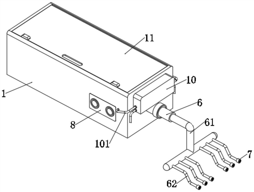
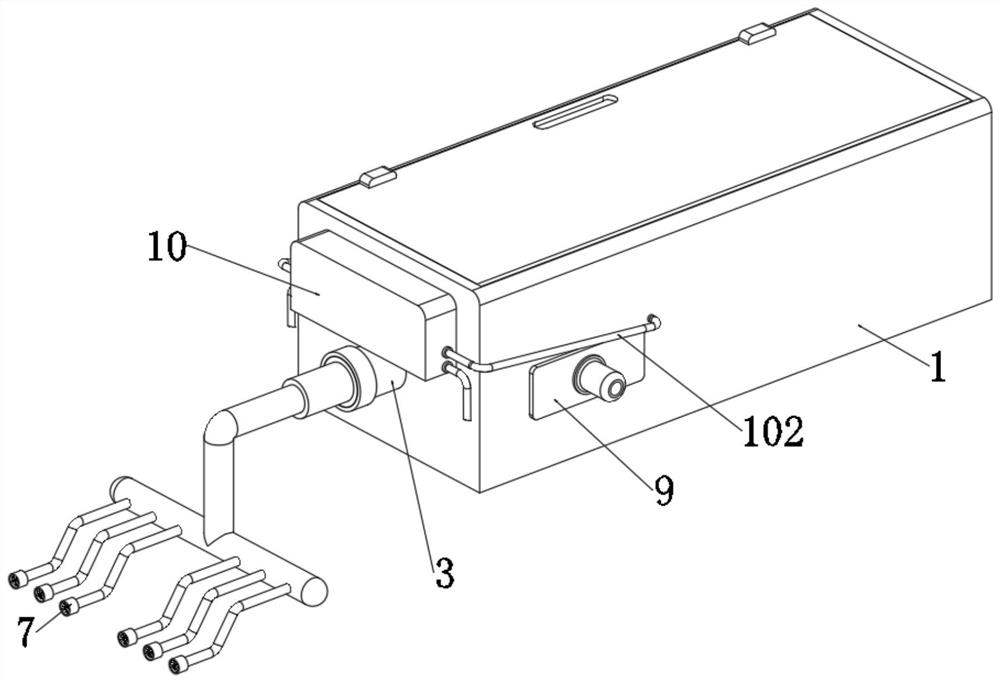
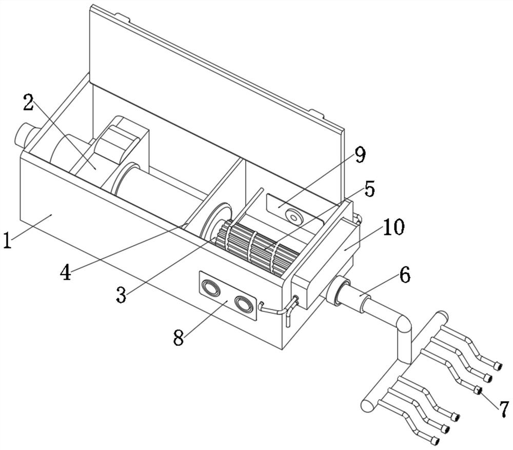
[0025] see Figure 1-5 , the present invention provides a technical solution: an improved large-scale ozone generator, comprising a cabinet body 1, an air pump body 2 is fixedly installed on one side of the cabinet body 1, and a generator body is fixedly installed at the output end of the air pump body 2, The side of the generator body away from the air pump body 2 is fixedly connected with an oxygen delivery tube 3, and the side of the generator body close to...


PUM


Abstract

The invention discloses an improved large ozone generator which comprises a case body, an air pump body is fixedly mounted on one side of the interior of the case body, a generator body is fixedly mounted at the output end of the air pump body, and an oxygen catheter is fixedly connected to the side, away from the air pump body, of the generator body; and one side, close to the oxygen catheter, of the generator body is fixedly sleeved with a partition plate. By arranging an anti-blocking assembly, when the ozone generator is used for high-speed output of ozone, the ozone enters an oxygen spraying frame through an oxygen conveying pipe, a connecting pipe, a T-shaped multi-way pipe and an air dredging hose to blow and drive fan blades to stably rotate, so that a driving shaft is driven to stably rotate in a connecting frame, a three-legged rod is driven to stably rotate, and a cleaning pad is driven to rotate to clean the outer wall of an anti-blocking disc, so that the situation that sundries are attached to the outer wall of the anti-blocking disc, blockage is caused, and ozone spraying is affected is effectively prevented, and the ozone output effect of the ozone generator is improved.

Description

technical field [0001] The invention relates to the technical field of ozone generators, in particular to an improved large-scale ozone generator. Background technique [0002] Ozone, also known as superoxide, is an allotrope of oxygen. At room temperature, it is a gas with a special stench. Liquid ozone is dark blue, and solid ozone is purple-black. Ozone water has strong oxidizing properties and is a broad-spectrum disinfectant without secondary pollution. It is widely used in aquaculture. Aquaculture farmers can use large-scale ozone generators To improve water quality, when large-scale ozone generators perform ozone to improve water quality, they usually use an air pump to input external gas into the generator to generate ozone, and discharge the generated ozone through the oxygen pipeline. Because the large-scale ozone generator is producing ozone When the power is large, heat will be generated, and the heat will be channeled through the oxygen tube with the ozone. Aft...

Claims


Application Information

Patent Timeline
IPC IPC(8): C01B13/10C02F1/78
CPCC01B13/10C02F1/78Y02P20/10
Inventor 葛淑芳
Owner 宿州龙润生物科技有限公司
Features
  • Generate Ideas
  • Intellectual Property
  • Life Sciences
  • Materials
  • Tech Scout
  • Unparalleled Data Quality
  • Higher Quality Content
  • 60% Fewer Hallucinations
Learn More