Internal combustion engine in-cylinder braking device

A technology of braking device and internal combustion engine, which is applied in valve device, engine control, machine/engine, etc., can solve the problems of not considering valve clearance adjustment, complex structure, etc.

Active Publication Date: 2021-07-30
宁波东方动力部件有限公司
View PDF6 Cites 3 Cited by
  • Summary
  • Abstract
  • Description
  • Claims
  • Application Information

AI Technical Summary

Problems solved by technology

However, its structure is complex, and the adjustment of the valve cl

Method used


Image

  • Internal combustion engine in-cylinder braking device
  • Internal combustion engine in-cylinder braking device
  • Internal combustion engine in-cylinder braking device

Examples


Embodiment 1

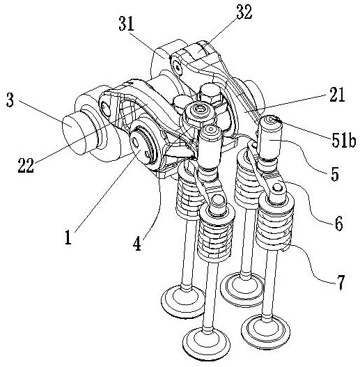
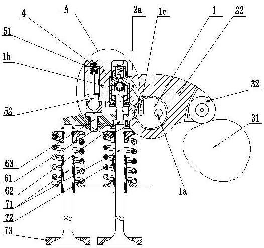
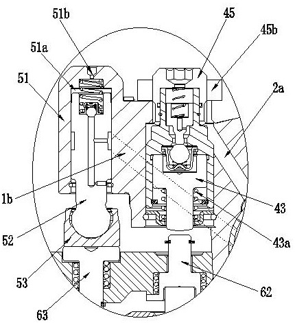
[0034] Embodiment one, such as Figure 1 to Figure 7 As shown, an internal combustion engine in-cylinder braking device includes a rocker shaft 1, and the rocker shaft 1 is equipped with an intake rocker assembly 21 and an exhaust rocker assembly 22, and the intake rocker The assembly 21 and the exhaust rocker assembly 22 are respectively provided with a roller assembly 32 which is matched with the cam 31 on the camshaft 3, and the exhaust rocker assembly 22 is provided with a brake valve assembly 4. The valve ends of the air rocker arm assembly 21 and the exhaust rocker arm assembly 22 are respectively provided with a hydraulic tappet assembly 5, and the hydraulic tappet assembly 5 cooperates with the valve bridge assembly 6, and the valve bridge assembly 6 includes a valve Bridge 61, the valve bridge 61 matched with the exhaust rocker arm assembly 22 is provided with a push rod 62 elastically connected to the valve bridge 61, the push rod 62 is matched with the brake valve a...

Embodiment 2

[0050] Embodiment two, such as Figure 8 and Figure 9 As shown, the structure of the internal combustion engine in-cylinder braking device in this embodiment is similar to that in Embodiment 1, the difference is that in this embodiment, the valve bridge assembly 6 is a non-compensated valve bridge assembly, and the valve bridge assembly 6 There is no need to set the limit pin shaft 63 in the middle. In this embodiment, the exhaust cam profile does not compensate for the initial clearance of the valve.

[0051] working principle:

[0052] Under normal operating conditions of the internal combustion engine:

[0053] The intake rocker arm assembly 21, the exhaust rocker arm assembly 22 and the valves operate in a normal state.

[0054] Under the action of the exhaust cam, the exhaust rocker arm assembly 22 runs according to the profile track of the exhaust cam, and the hydraulic tappet assembly 5 is under the action of the third elastic member 55, and the tappet 52 passes th...


PUM


Abstract

The invention discloses an internal combustion engine in-cylinder braking device which comprises a rocker arm shaft, an air inlet rocker arm assembly and an exhaust rocker arm assembly. A braking valve assembly is arranged on the exhaust rocker arm assembly, hydraulic tappet assemblies are arranged at the valve ends of the rocker arm assemblies respectively, and the hydraulic tappet assemblies are matched with valve bridge assemblies. Each hydraulic tappet assembly comprises a shell, tappets are elastically matched in the shells, elephant feet are assembled on ball heads of the tappets, main oil ducts are axially arranged on the tappets, first one-way valve assemblies are arranged between the upper ends of the main oil ducts and an upper oil cavity, exhaust holes are formed in the shells, oil inlet holes and oil outlet holes are radially formed in the tappets, and reducing sections are arranged on the oil outlet holes. A lubricating oil channel in the rocker arm shaft communicates with the oil inlet holes through oil inlet channels, the oil outlet holes communicate with the inner cavities of the elephant feet, and a braking control oil channel communicates with the braking valve assembly through a braking oil channel on a rocker arm. The internal combustion engine in-cylinder braking device has the advantages that the structure is reasonable, the braking reliability and safety can be improved, the valve clearance does not need to be adjusted, engine noise can be reduced, and NVH is improved.

Description

technical field [0001] The invention relates to the technical field of automobile internal combustion engine manufacturing, in particular to an internal combustion engine cylinder braking device. Background technique [0002] With the continuous development of my country's road transportation, all kinds of medium and heavy commercial vehicles have entered the transportation field of different industries, and the safety during transportation is the top priority. The braking performance of various medium and heavy-duty commercial vehicles during transportation is very important, especially when driving downhill, the driving safety is not optimistic. When going downhill for a long time, the driver must frequently use the brakes to decelerate the brakes, which will cause the brakes to overheat, causing the brakes to gradually decrease in braking efficiency or even fail. It is more serious on rugged mountain roads and long-slope roads. Some medium and heavy-duty commercial vehic...

Claims


Application Information

Patent Timeline
IPC IPC(8): F01L13/06F01L9/10F01L1/18F02D13/04
CPCF01L13/06F01L1/18F02D13/04
Inventor 马振万
Owner 宁波东方动力部件有限公司
Why Eureka
Try Eureka