Hygienic flange-type tube joint thermal expansion area for gasket

A technology of flange joints and gaskets, applied in flange connection, pipe/pipe joint/pipe fitting, through components, etc., can solve the problems of polluted system, reduced sealing performance of the boundary interface of holes, and the system cannot meet the required fluid velocity.

Inactive Publication Date: 2003-12-24
SWAGELOK CO
View PDF3 Cites 0 Cited by
  • Summary
  • Abstract
  • Description
  • Claims
  • Application Information

AI Technical Summary

Problems solved by technology

Gaskets in a restrictive state may prevent the system from meeting the required fluid velocities and therefore failing to meet administrative regulations
The second problem, cell shear, is caused by the impingement of vulnerable microorganisms on the extruded gasket, which results in the destruction of the cells that are the target product of the bioprocess
The third problem, system contamination, is caused by prolonged exposure to process conditions, especially steam, where extruded gaskets become brittle and break into pieces, which contaminate the system
When this happens, only a small compressive force acts on the gasket material that remains inside the device, which can cause the device to loosen
In some cases, only one heating cycle can result in reduced sealing of the boundary surface of the hole, which allows process fluid to easily enter the sealing area and become trapped
Standing fluid cannot be removed without disassembly and can cause contamination of the same batch or subsequent batches

Method used


Image

  • Hygienic flange-type tube joint thermal expansion area for gasket
  • Hygienic flange-type tube joint thermal expansion area for gasket
  • Hygienic flange-type tube joint thermal expansion area for gasket

Examples


Embodiment Construction

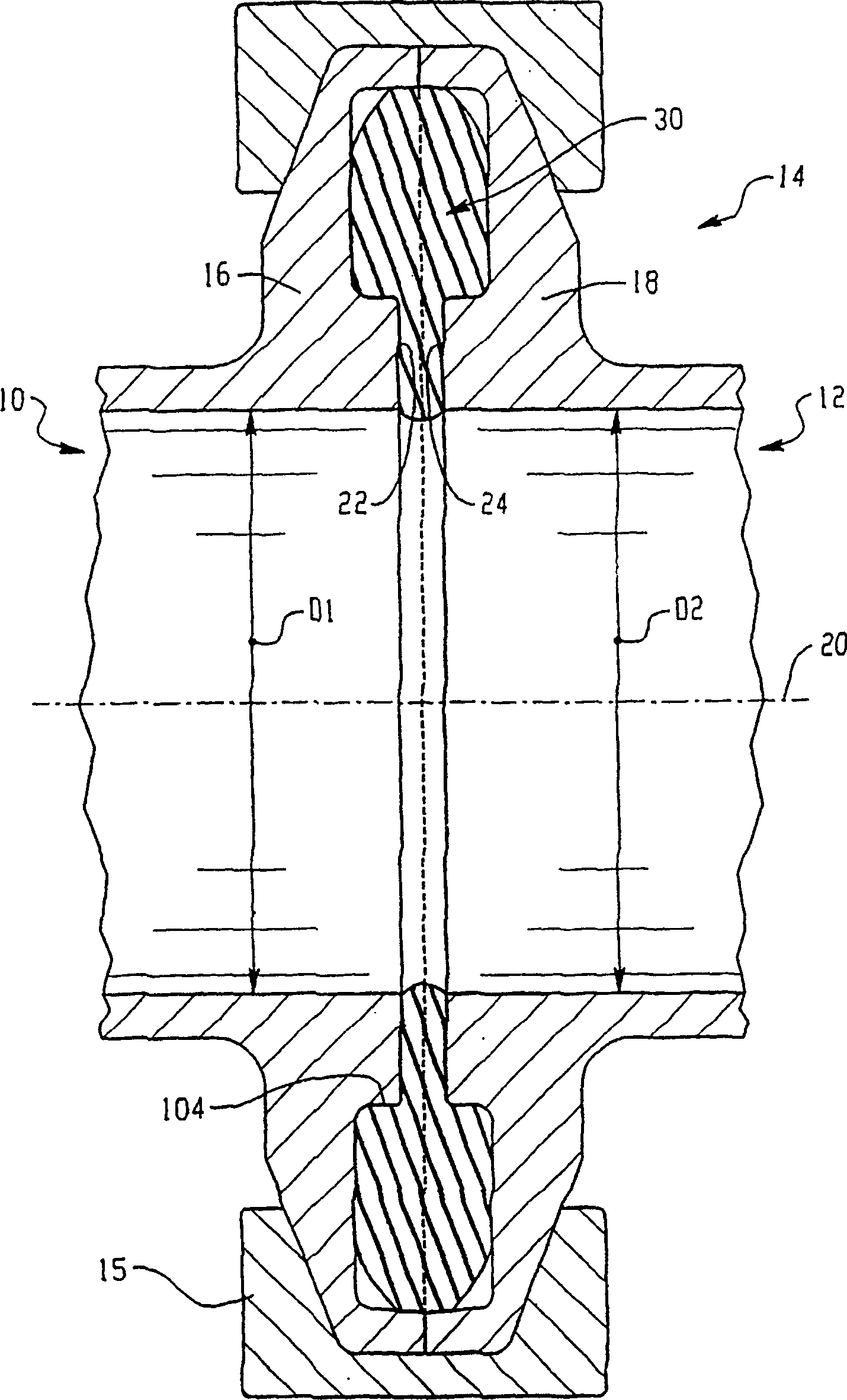
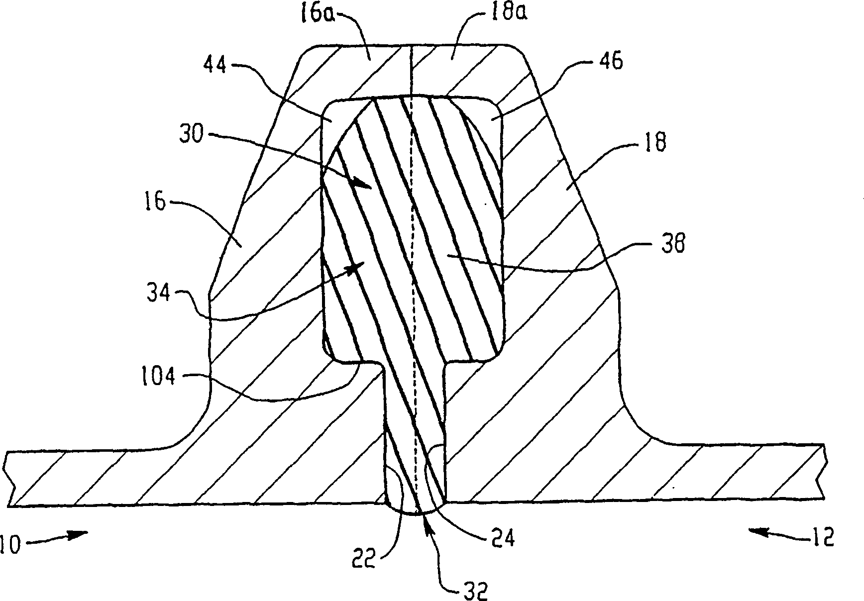
[0026] Referring now to the accompanying drawings, these figures are only used to illustrate preferred embodiments of the present invention, without limiting the meaning of the present invention, figure 1 A pair of axially aligned cylindrical tubes or tube ends 10 , 12 are shown joined together in sealed form by a flanged coupling assembly 14 . The tube ends 10 , 12 each have a uniform open inner diameter D1 , D2 , which have the same inner diameter and are arranged aligned close to each other. An annular continuous radially extending flange 16 , 18 is formed on each pipe end 10 , 12 . This flange enables the two pipe ends to be clamped into assembled condition by conventional clamping rings 15 , which clamps are only schematically shown in the figures. While the flanges 16,18 could be formed as separate components and attached to the pipe ends by suitable means, in this embodiment they are shown integrally formed on the respective pipe ends 10,12.

[0027] Each flange 16 , ...


PUM


Abstract

A sealing gasket for insertion into a circumferentially continuous groove of a flange joint for joining axially aligned tube ends, the flange joint being of the type having axially opposed flanges (16, 18) at the tube ends to form a groove (30) therebetween when the joint is assembled, the groove being formed by axially opposed seal faces (22, 24) and radial end faces (16a, 18a) of the flanges, the groove comprising a groove first portion (32) that is open to an interior flow passage of the tubes and a second portion (34) that extends radially outward from the groove first portion, the gasket having a gasket first portion that seals the groove first portion and a gasket second portion that extends from the gasket first portion and into the groove second portion; the gasket second portion being axially compressed when the joint is assembled and engaging with the radial end faces to produce a radial compression of the gasket; the gasket second portion having a volume that is less than volume of the groove second portion to form an expansion space (44) in the groove second portion when the joint is assembled.

Description

[0001] priority claim [0002] This application claims the benefit of the following provisional application, entitled "Improved Sanitary Fittings Having Gasket Thermal Expansion Regions": Unassigned Provisional Application Serial No. 60 / 0383993, filed February 18, 1998, Express Mail No. No. EM178206756US, the contents of which application are incorporated herein by reference. technical field [0003] The present invention relates to pipe technology or pipe connection and pipe joint technology, in particular to flanged pipe joints with improved relationship between sealing surfaces and associated gaskets. Background technique [0004] Flanged pipe joints have gaskets of flexible material such as elastomeric, plastic, etc. that are clamped between the sealing end surfaces of opposing flanges. These fittings are often used in sanitation systems where stagnant fluid is highly undesirable. These systems are usually constructed so that the tubes are arranged at a slight angle of...

Claims


Application Information

Patent Timeline
IPC IPC(8): F16L23/026F16L23/028F16L23/024F16L23/032F16L23/16F16L23/22
CPCF16L23/04F16L23/16F16L23/22F16L23/18
Inventor R·L·库恩斯A·S·沙希D·A·斯利菲
Owner SWAGELOK CO
Why Eureka
Try Eureka