Cutting correction device based on numerical control lathe
A technology of CNC lathes and mounting blocks, applied in positioning devices, driving devices, clamping, etc., can solve problems such as inability to adjust and clean, and achieve the effects of easy use, improved use effect, and improved flushing effect
- Summary
- Abstract
- Description
- Claims
- Application Information
AI Technical Summary
Problems solved by technology
Method used
Image

Examples
Embodiment 1
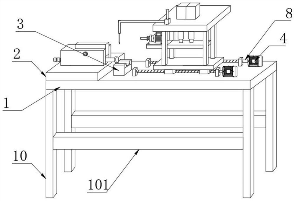
[0030] Such as Figure 1-6 As shown, the embodiment of the present invention provides a CNC lathe cutting correction device, including a workbench 1, the top of the workbench 1 is fixedly connected with a first locking plate 2, a second mounting block 3 and a drive motor 4 in sequence from left to right, The top of the first locking plate 2 is fixedly connected with a clamping device, the top of the second mounting block 3 is fixedly connected with a connecting block 5, the top of the connecting block 5 is provided with a U-shaped guide groove 6, and the bottom of the inner cavity of the U-shaped guide groove 6 is fixedly connected with a The magnet sheet 7 is adsorbed, the top of the workbench 1 is provided with a moving mechanism, the output end of the driving motor 4 is fixedly connected with a fixed connecting rod 8, the top of the moving mechanism is provided with an adjustment and cleaning mechanism, and the bottom of the workbench 1 is fixedly connected with a support le...
Embodiment 2
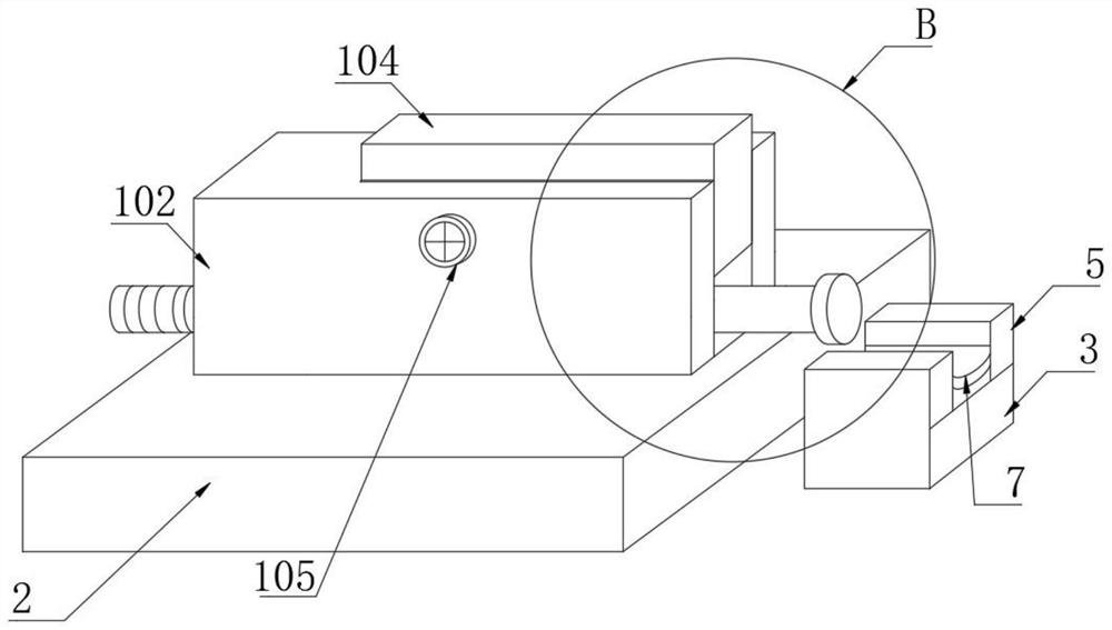
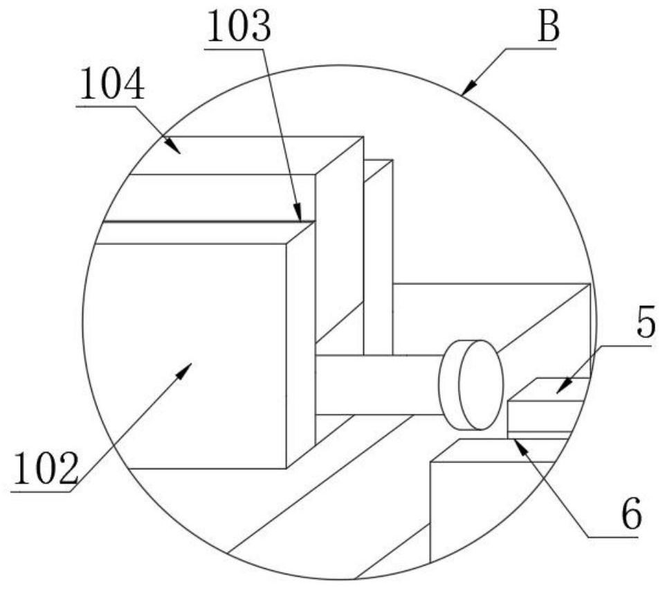
[0032] Such as figure 2 and image 3 , the clamping device includes a clamping plate 102, a clamping groove 103 is opened through the top of the clamping plate 102, a limit block 104 is arranged inside the clamping groove 103, a fixing bolt 105 is arranged on the outer surface of the clamping plate 102, and the fixing bolt 105 is close to The end of the clamping plate 102 passes through the clamping plate 102 and the limiting block 104 and extends to the outside of the clamping plate 102 , so as to install the limiting block 104 inside the clamping groove 103 . Such as Figure 4 and Figure 5 , the moving mechanism includes a moving lead screw 106, the outer wall of the moving lead screw 106 is rotatably connected with two moving blocks 107, one end of the moving lead screw 106 is rotatably connected with a first moving support block 11, and the other end of the moving lead screw 106 is rotatably connected with a second Move the supporting block 111, the end of the moving ...
Embodiment 3
[0034] Such as Figure 6 , the adjustment and cleaning mechanism includes an adjustment cylinder 115, the bottom of the adjustment cylinder 115 is fixedly connected with the adjustment sleeve plate 114, the piston end of the adjustment cylinder 115 is fixedly connected with a first adjustment movable plate 116, and the outer wall of the first adjustment movable plate 116 is fixedly connected with a second Adjust movable plate 117, so that on the first adjusted movable plate 116 I have lived in the second adjusted movable plate 117. Such as Figure 6 , the top of the second adjustable movable plate 117 is fixedly connected with a cutting motor 118, the output end of the cutting motor 118 is fixedly connected with a cutting rod 119, and the end of the cutting rod 119 is fixedly connected with a cutting installation cutter head 120, so that the cutting installation can be installed on the cutting rod 119 Blade 120. Such as Figure 6 , the top of the adjusting sleeve plate 114 ...
PUM
 Abstract
Description
Claims
Application Information
PatSnap Eureka turns technology decisions into work you can execute. Powered by our Innovation Knowledge Graph, it runs expert workflows across engineering, life sciences, materials and intellectual property. Get your review-ready output in minutes.


