Combined bearing double-layer well wall and construction method thereof

A construction method and technology for outer well wall, which are applied in vertical shaft equipment, earth-moving drilling, wellbore lining, etc., can solve the problem of inability to improve the filling effect of inter-wall grouting on the seepage channel of well wall, etc., and achieve a favorable grouting effect. , Improve the sealing water performance and increase the effect of grouting pressure

Active Publication Date: 2021-08-03
CHINA UNIV OF MINING & TECH
View PDF9 Cites 1 Cited by
  • Summary
  • Abstract
  • Description
  • Claims
  • Application Information

AI Technical Summary

Problems solved by technology

However, the double-layer composite well wall cannot improve the filling effect of interwall grouting on the seepage channel of the well wall

Method used


Image

  • Combined bearing double-layer well wall and construction method thereof

Examples


Embodiment 1

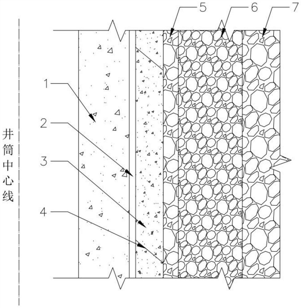
[0028] A double-layer shaft wall with combined bearings, including an inner shaft wall 1 and an outer shaft wall 3, the outer shaft wall 3 is excavated and poured in sections, and there are construction joints 4 between the sections of the outer shaft wall 3; The well wall 1 is formed by continuous pouring; there is a gap between the inner well wall 1 and the outer well wall 3 , and a micro-expansion grouting material is injected into the gap to form a micro-expansion interlayer 2 .

[0029] In this embodiment, the inner shaft wall 1 is formed by continuous pouring from bottom to top using low-heat of hydration micro-expansion concrete that meets the design strength.

[0030] Wherein, the outer shaft wall 3 is poured in sections from top to bottom, and there are construction joints 4 between adjacent sections of the shaft wall. The inner shaft wall 1 is poured continuously from bottom to top, without construction joints 4, and the integrity is good.

[0031] In this embodimen...

Embodiment 2

[0039] This embodiment is a construction method for manufacturing the joint bearing double-layer well wall provided in embodiment 1, including the following steps:

[0040] S10. Excavating in sections from top to bottom and pouring the outer well wall 3 .

[0041] S20. Continuously pouring the micro-expansion inner shaft wall 1 from bottom to top; during the pouring process, multiple groups of grouting pipes are pre-buried vertically on the inner shaft wall 1 for the later inner shaft wall and outer shaft wall grouting in between.

[0042] In another embodiment, after the pouring of the inner well wall 1 is completed, multiple sets of grouting pipes are installed by drilling vertically spaced holes in the inner well wall 1 for later grouting between the inner well wall and the outer well wall. .

[0043] S30. After the construction of the inner well wall 1 is completed, the micro-expansion grouting material is injected between the inner well wall 1 and the outer well wall 3 ...


PUM


Abstract

The invention discloses a combined bearing double-layer well wall and a construction method thereof, and belongs to the technical field of double-layer well wall construction. The combined bearing double-layer well wall comprises an inner-layer well wall and an outer-layer well wall, the outer-layer well wall is formed by tunneling and pouring in sections, and construction joints exist between the sections of the outer-layer well wall; the inner-layer well wall is formed by continuous casting; and a gap is formed between the inner-layer well wall and the outer-layer well wall, and a micro-expansion grouting material is injected into the gap to form a micro-expansion interlayer. The micro-expansion grouting material is adopted for grouting between the inner-layer well wall and the outer-layer well wall, and the solidified slurry can tightly bond the inner-layer well wall and the outer-layer well wall and compactly fill water seepage channels in the outer-layer well wall and the stratum close to the well wall.

Description

technical field [0001] The invention belongs to the technical field of double-layer shaft wall construction, and in particular relates to a joint bearing double-layer shaft wall and a construction method thereof. Background technique [0002] Wellbores in water-rich formations in my country are often excavated by artificial freezing, and double-layer reinforced concrete well walls (referred to as "double-layer well walls") or double-layer reinforced concrete composite well walls with plastic interlayers (referred to as "double-layer composite well walls") are often used. well wall") for support. The wellbore is the lifeline connecting the ground and the underground. Therefore, within the service life, the wellbore as a support structure must have strong bearing capacity (withstand formation and groundwater pressure) and high water sealing performance (the water inflow from the wellbore should meet the use requirements). [0003] The double-layer well wall is composed of inne...

Claims


Application Information

Patent Timeline
Patent Type & Authority Applications(China)
IPC IPC(8): E21D5/00E21D5/04E21D5/06E21D5/11E21D5/12
CPCE21D5/00E21D5/04E21D5/06E21D5/11E21D5/12
Inventor 杨维好杨志江任彦龙张驰张涛韩涛黄家会
Owner CHINA UNIV OF MINING & TECH
Why Eureka
Try Eureka