Agricultural weeding machine with good protection effect
A weeding machine and agricultural technology, which is applied in the field of weeding machines, can solve the problems of easily hurting people, getting involved in soil, and inconvenient movement of the body, and achieves the effects of convenient shielding and protection, convenient centralized cleaning, and good protection effect
- Summary
- Abstract
- Description
- Claims
- Application Information
AI Technical Summary
Problems solved by technology
Method used
Image
Examples
Embodiment 1
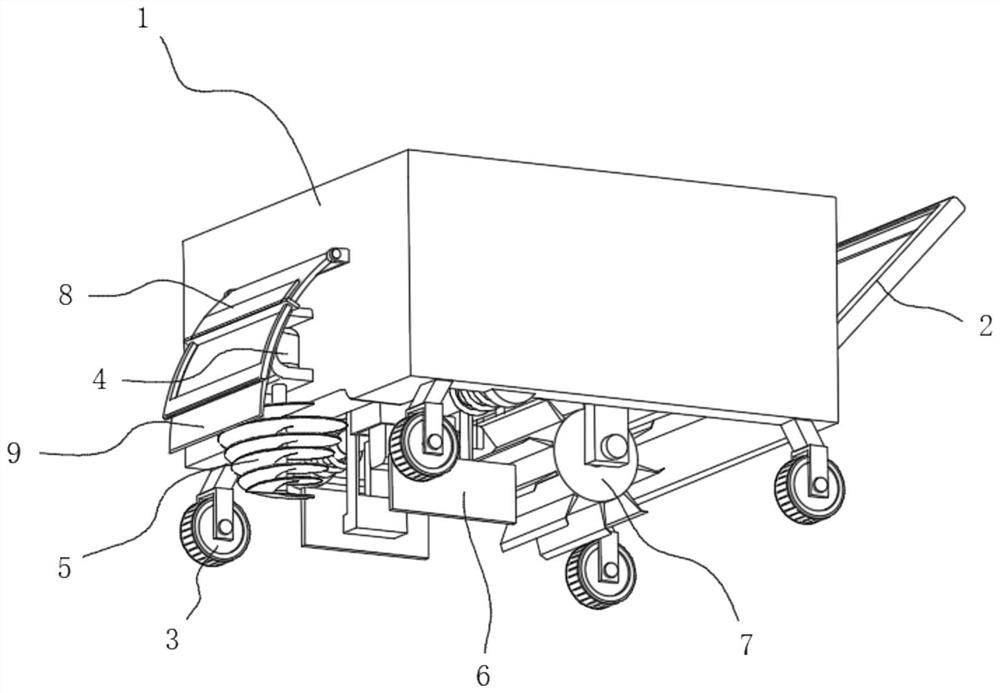
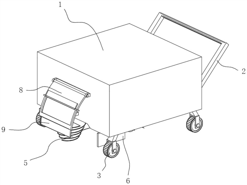
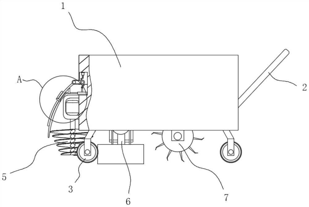
[0031] see Figure 1-8 , the present invention provides a technical solution: an agricultural weeder with good protective effect, comprising a body 1, a push handle 2 is fixedly connected to the outer wall on the right side of the body 1, and a roller 3 is fixedly connected to the four corners of the bottom of the body 1. The left side outer wall of 1 is fixedly connected with a rotating motor 4, and the bottom of the rotating motor 4 is connected with a lawn mowing wheel 5, and the top inner wall of the body 1 is fixedly connected with a pushing device 6, and the top inner wall of the body 1 is located at the pushing device 6. The right side is fixedly connected with the weeding wheel 7 by being provided with a mobile cylinder, and one side of the weeding wheel 7 is rotatably connected with a weeding motor, and the left side outer wall of the body 1 is provided with a rotating device 8.
[0032] The rotating device 8 comprises a rotating cover plate 801, one side of the rotat...
Embodiment 2
[0035] see Figure 1-8 As shown, on the basis of Embodiment 1, the present invention provides a technical solution: the pushing device 6 includes a hydraulic cylinder 601, the bottom of the hydraulic cylinder 601 is fixedly connected with a trapezoidal block 602, and the bottom of the trapezoidal block 602 is fixedly connected with a connecting block 603, the inner walls on both sides of the body 1 are fixedly connected with the limit slide bar 604, the outer wall of the limit slide bar 604 is sleeved with the limit spring 605, the outer wall of the limit slide bar 604 is slidably connected with a slide frame 606, and the bottom of the slide frame 606 A pusher plate 607 is fixedly connected, and a connecting frame 608 is fixedly connected to the side of the limit slide bar 604 away from the inner wall of the body 1. The top of the hydraulic cylinder 601 is fixedly connected to the top inner wall of the body 1, and the connecting block 603 runs through the inside of the connecti...
Embodiment 3
[0038] see Figure 1-8 As shown, on the basis of Embodiment 1 and Embodiment 2, the present invention provides a technical solution: one side of the rotating device 8 is provided with a telescopic cover 9, and one side of the telescopic cover 9 is fixedly connected with a sliding block 10, The side of the sliding block 10 away from the telescopic cover 9 is movably connected with a movable rod 11, the side of the movable rod 11 far away from the sliding block 10 is movably connected with a telescopic cylinder 12, and the side of the telescopic cylinder 12 close to the movable rod 11 is fixedly connected with a push block 13.
[0039] In the present embodiment, through the telescopic cover plate 9 that is set, it is convenient to protect the mowing wheel 5, and the telescopic cover plate 9 is movable simultaneously, and the push block 13 is driven by starting the telescopic cylinder 12 to move, and the push block 13 moves with the rotation cover plate 801 contacts, and the rot...
PUM
 Abstract
Description
Claims
Application Information
 - R&D
- Intellectual Property
- Life Sciences
- Materials
- Tech Scout
- Unparalleled Data Quality
- Higher Quality Content
- 60% Fewer Hallucinations
Browse by: Latest US Patents, China's latest patents, Technical Efficacy Thesaurus, Application Domain, Technology Topic, Popular Technical Reports.
© 2025 PatSnap. All rights reserved.Legal|Privacy policy|Modern Slavery Act Transparency Statement|Sitemap|About US| Contact US: help@patsnap.com


