Automatic medicine dispensing device
A technology of automatic dispensing and dispensing table, which is applied in the field of medical devices, can solve the problems of affecting work efficiency, consuming a large dispensing time, and not being able to convert powder medicine into liquid medicine, so as to reduce labor intensity, reduce dispensing time and improve work efficiency. Effect
- Summary
- Abstract
- Description
- Claims
- Application Information
AI Technical Summary
Problems solved by technology
Method used
Image
Examples
Embodiment 1
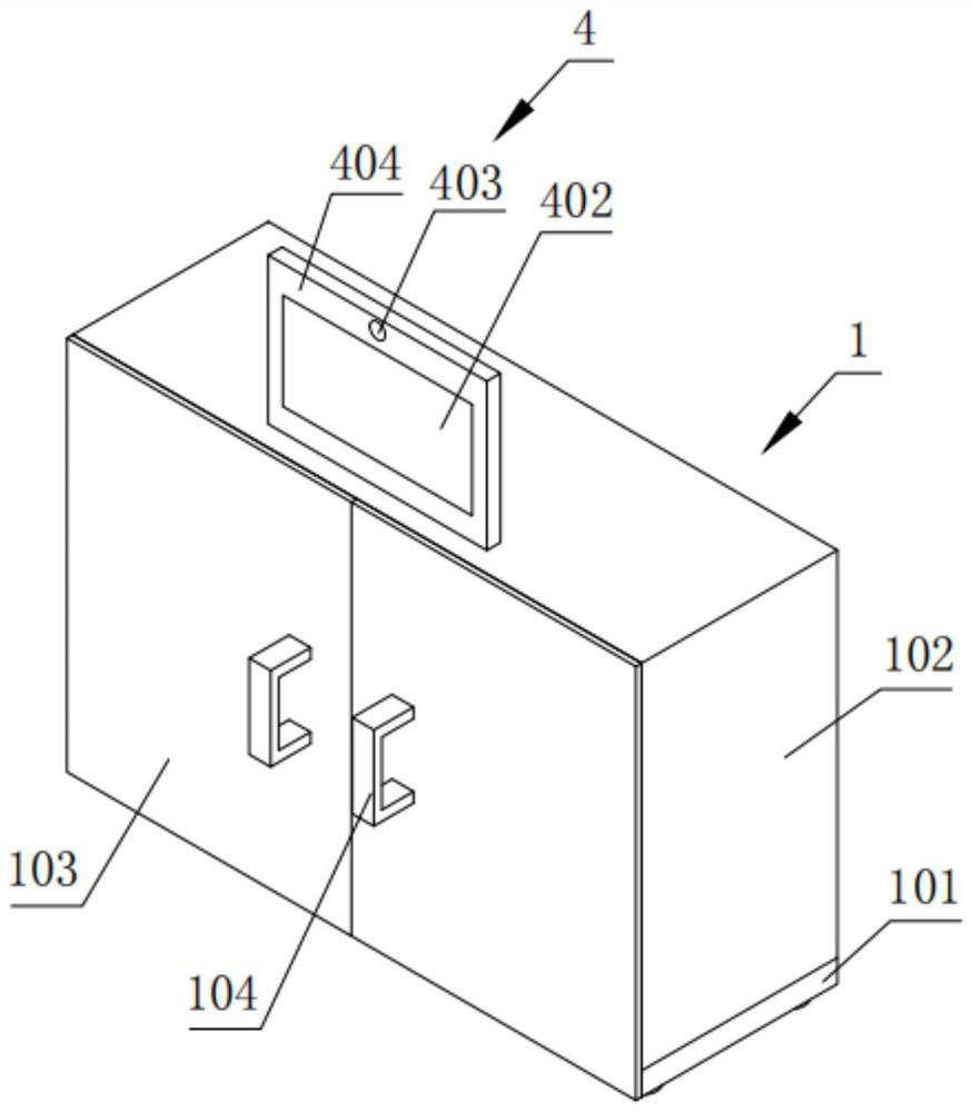
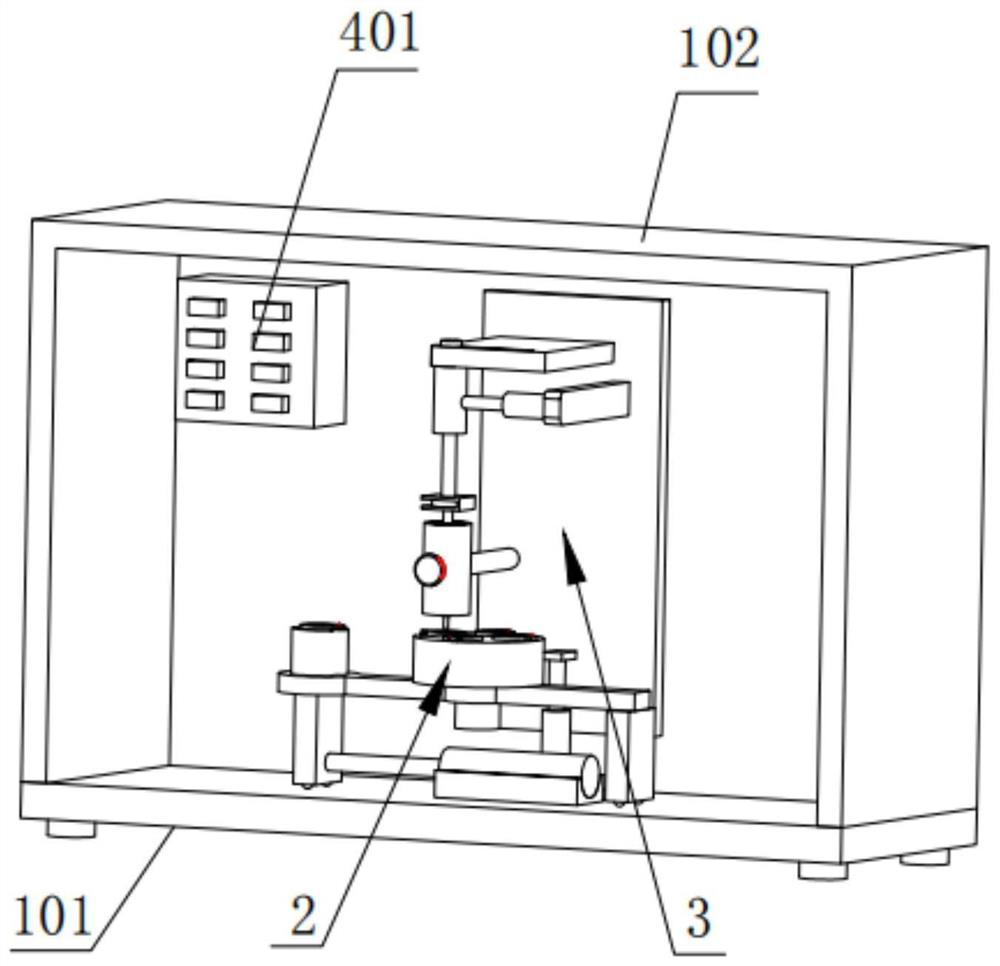
[0054] Such as figure 1 and 2 As shown, this embodiment provides an automatic dispensing device. In order to realize the purpose of automatically washing powder medicine into liquid medicine, it can effectively reduce the labor intensity of medical staff, and it is particularly important to effectively reduce the time for dispensing and effectively improve work efficiency. The automatic dispensing device is composed of a main structure 1, a dispensing table 2, a medicine preparation mechanism 3 and a control mechanism 4;
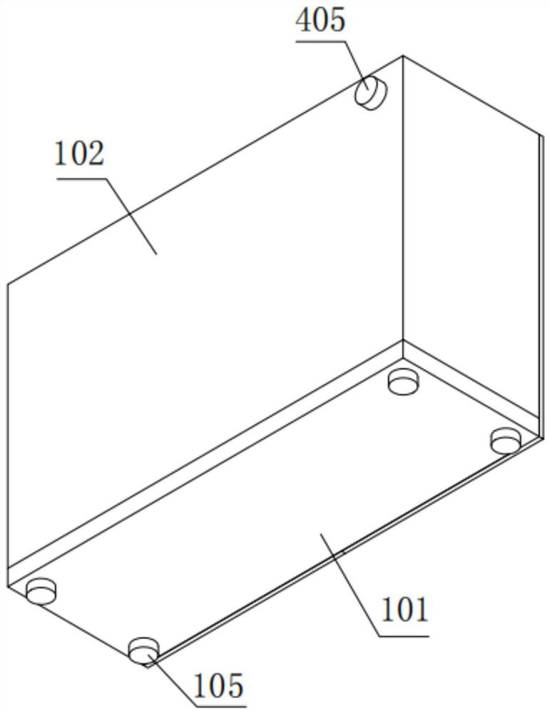
[0055] Among them, such as Figure 1-3 As shown, in order to form a closed space inside the main structure 1, so that the dispensing space can avoid dust entering, improve the cleanliness, and prevent the prepared medicinal solution from being polluted, the main structure 1 is composed of a bottom plate 101, a casing 102 and a door panel 103 structure, the base plate 101 is horizontally arranged, the shell 102 is fixedly installed on the upper part of the ...
Embodiment 2
[0067] Such as Figure 4 , 6 As shown in and 8, the difference between this embodiment and embodiment 1 is that in order to realize that the automatic dispensing device can prepare multiple bottles of medicinal liquid at one time, which can effectively improve the working efficiency of dispensing, the first cylindrical base 203 is rotated and installed On the upper part of the supporting beam 202, at least three fixed grooves arranged at an equal angle in the circumferential direction are arranged on the first cylindrical base 203, and the second cylindrical base 204 is fixedly installed on the upper part of the supporting beam 202, and A fixing slot is provided on the second cylindrical base 204. In order to enable the first cylindrical base 203 to rotate to switch the upper fixing slot, a motor 207 is also fixedly installed on the bottom of the support beam 202, and the The rotating shaft of motor 207 runs through support crossbeam 202 and is fixedly connected with the bott...
Embodiment 3
[0070] Such as Figure 4 As shown, the difference between this embodiment and Embodiment 2 is that the medicine charging mechanism 3 also includes an assembly plate 305, and a chute 309 is provided on the assembly plate 305, and a slide block 308 is slidably installed in the chute 309, and the slide The bottom of block 308 is fixedly connected with the upper end of the 4th electric push rod 304, can utilize chute 309 to cooperate with slide block 308 to provide an upward pulling force to the 4th electric push rod 304, can lower the 4th electric push rod 304 to the 4th electric push rod 304. The down force of the three electric push rods 307 ensures the service life of the third electric push rod 307.
PUM
 Abstract
Description
Claims
Application Information
 - R&D
- Intellectual Property
- Life Sciences
- Materials
- Tech Scout
- Unparalleled Data Quality
- Higher Quality Content
- 60% Fewer Hallucinations
Browse by: Latest US Patents, China's latest patents, Technical Efficacy Thesaurus, Application Domain, Technology Topic, Popular Technical Reports.
© 2025 PatSnap. All rights reserved.Legal|Privacy policy|Modern Slavery Act Transparency Statement|Sitemap|About US| Contact US: help@patsnap.com


