Piston pin grinding device for machining

A technology for mechanical processing and piston pins, which is applied in the direction of grinding drive devices, metal processing equipment, grinding machines, etc., can solve the problems of low efficiency of piston pin grinding and processing, reduce equipment investment costs, save time and cost, and improve grinding efficiency and quality effects

Inactive Publication Date: 2021-08-06
义乌市今朝创意设计有限公司
View PDF6 Cites 0 Cited by
  • Summary
  • Abstract
  • Description
  • Claims
  • Application Information

AI Technical Summary

Problems solved by technology

[0003] The object of the present invention is to provide a piston pin grinding device for mechanical processing, which solves the problem of low efficiency of piston pin grinding in the prior art

Method used


Image

  • Piston pin grinding device for machining
  • Piston pin grinding device for machining
  • Piston pin grinding device for machining

Examples


Embodiment 1

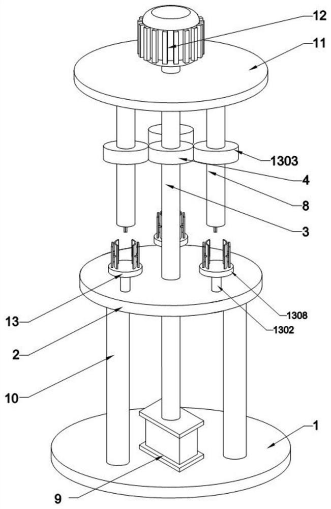
[0031] refer to Figure 1-3 , a piston pin grinding device for mechanical processing, comprising a base 1, an air compressor 9 is fixedly connected directly above the base 1, the exhaust pipe of the air compressor 9 communicates with the gas storage tank, and a second air compressor is arranged directly above the base 1 A support plate 2, the base 1 is fixedly connected to the first support plate 2 through a support rod 10, a second support plate 11 is arranged directly above the first support plate 2, and the first support plate 2 is connected to the second support plate 11 through a transmission rod 3 Connected, between the first support plate 2 and the second support plate 11, there are a number of grinding assemblies 13 distributed in a circular array centered on the central axis of the transmission rod 3; drive gears 4 are provided on the sides of the transmission rod 3; the second support The top bolt of the plate 11 is fixedly connected with the servo motor 12, the outp...

Embodiment Embodiment 1

[0041] When implementing Example 1, the inventor found that the driving gear 4 and the driven gear 1303 on the top of the first support plate 2 are easy to pinch the hair of the staff, causing personal injury to the staff, so the inventors based on Example 1 The following improvements have been made.

[0042] refer to Figure 5 , Figure 6 As shown, the outer side of the first support plate 2 is provided with a protective cover 8, the protective cover 8 is a cylindrical structure compatible with the first support plate 2, the top of the protective cover 8 is an open structure and the bottom is provided with a structure corresponding to the pole 10. Adaptive openings, the inside of the protective cover 8 is fixedly connected with three clips 5, and the outer wall of the first support plate 2 is provided with clip slots 6 that are compatible with the clips 5, and the three clip slots 6 are distributed in a circular array and the array The center is located on the central axis ...

Embodiment 3

[0045] Due to the existence of chamfers in the inner diameter of some existing piston pins, the chamfers of the piston pins cannot be ground according to the method of the above-mentioned embodiment 1, and it needs to be polished manually or using a special grinding equipment alone, which will occupy the workshop space. , and the equipment investment is large, so the inventor made the following further improvements on the basis of Embodiment 1.

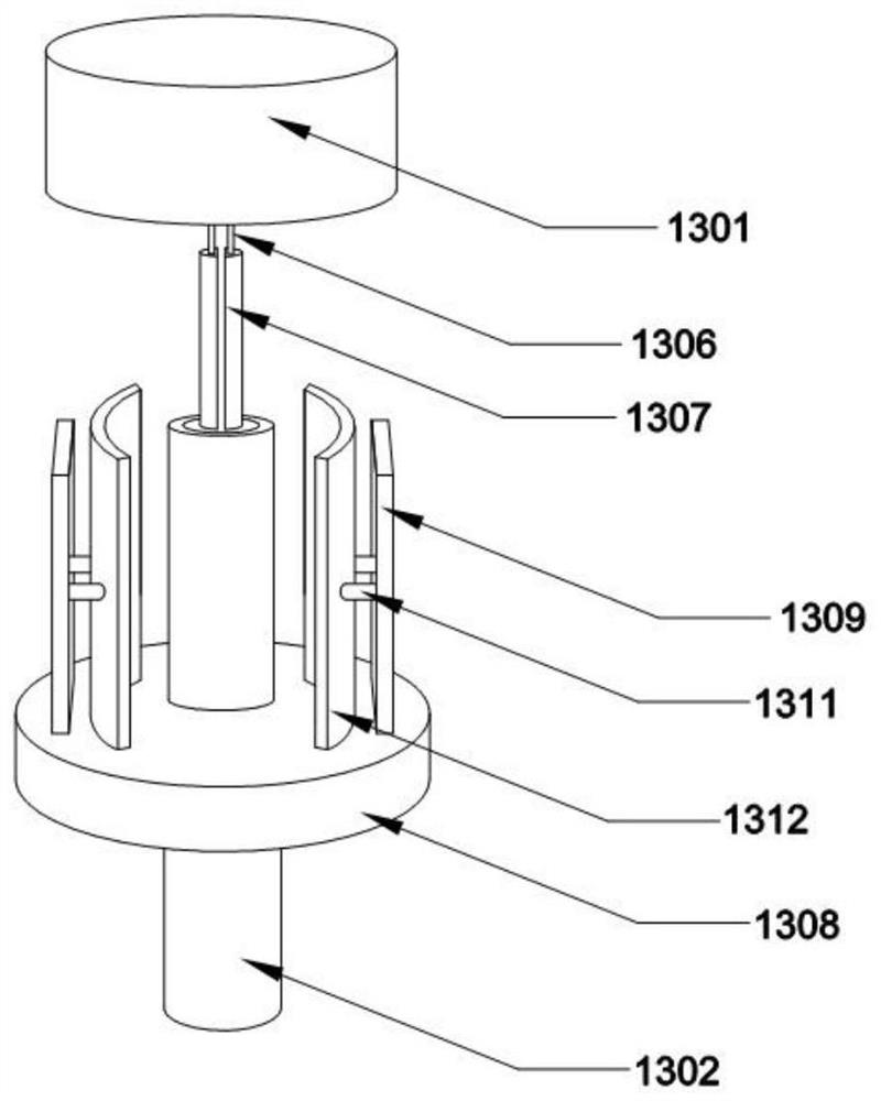
[0046] refer to Figure 7-9 As shown, the sliding assembly 1306 includes two vertical plates, and a "T"-shaped beam is arranged between the two vertical plates. It is fixedly connected with the first electromagnet 1307, and the side of the lower leg of the "T" beam is connected with the spacer 1305 through a spring.

[0047] One end of the spring on the left side of the spacer 1305 is connected to the side of the lower leg of the "T" beam, the other end of the spring on the left side of the spacer 1305 is connected to the second elec...


PUM


Abstract

The invention relates to the technical field of grinding devices, and particularly relates to a piston pin grinding device for machining. The piston pin grinding device for machining comprises a base, an air compressor is fixedly connected right above the base, a first supporting plate is arranged right above the base, the base is fixedly connected with the first supporting plate through a supporting rod, a second supporting plate is arranged right above the first supporting plate, and the first supporting plate is connected with the second supporting plate through a transmission rod. According to the piston pin grinding device for machining, through mutual cooperation of a first electromagnet, a second electromagnet, a third electromagnet, a pneumatic telescopic rod, a spring and the like, grinding of a chamfer of an inner ring of a piston pin is achieved, the problem that additional manual grinding is needed or special grinding equipment is independently used for grinding the chamfer of the inner ring of the piston pin is solved, the occupied space is reduced, and the equipment investment cost is reduced.

Description

technical field [0001] The invention relates to the technical field of grinding devices, in particular to a piston pin grinding device for machining. Background technique [0002] The piston pin is a cylindrical pin mounted on the piston skirt. Its middle part passes through the small head hole of the connecting rod and is used to connect the piston and the connecting rod. Its function is to transmit the gas force borne by the piston to the connecting rod, or to make the small head of the connecting rod drive the piston to move together. In order to reduce weight, the piston pin is generally made of high-quality alloy steel and processed into a hollow shape. As a commonly used component in machinery, the demand for piston pins is very huge, so a large number of production and processing have been obtained; External roughness will affect the use effect of the piston pin, so the grinding device for the piston pin is particularly important. However, during the use of the tra...

Claims


Application Information

Patent Timeline
IPC IPC(8): B24B5/04B24B5/08B24B9/04B24B27/00B24B41/06B24B47/00B24B47/12B24B47/14B24B47/16B24B47/22
CPCB24B5/08B24B5/047B24B27/0023B24B27/0076B24B41/067B24B47/00B24B47/14B24B47/16B24B9/04B24B47/12B24B27/0084B24B47/22
Inventor 朱堂葵
Owner 义乌市今朝创意设计有限公司
Why Eureka
Try Eureka