Uniform wetting device for non-woven fabric processing
A non-woven, uniform technology, applied in the direction of processing textile material equipment configuration, spraying/jetting textile material processing, etc., can solve the problems of waste, uneven wetting, etc., to improve environmental protection, improve uniformity, and improve reliability. Effect
- Summary
- Abstract
- Description
- Claims
- Application Information
AI Technical Summary
Problems solved by technology
Method used
Image
Examples
Embodiment 1
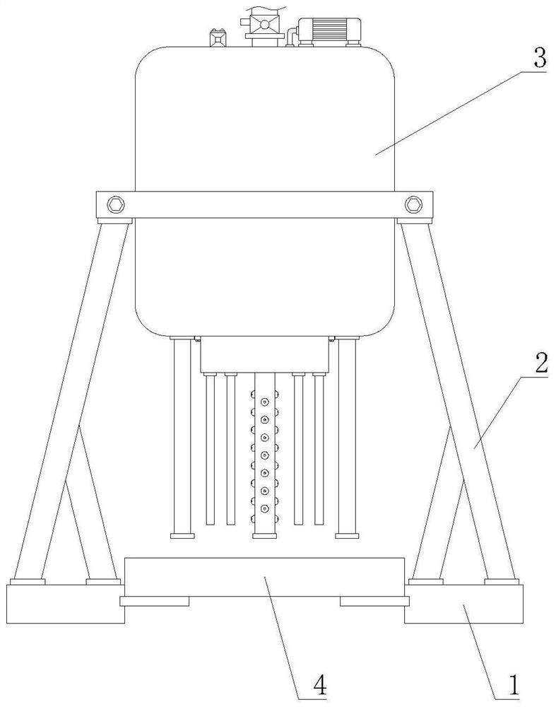
[0040] Such as Figure 1-7 As shown, the present invention provides a uniform wetting device for non-woven fabric processing, including a base 1, a bracket 2 is fixedly installed on the top of the base 1, and a uniform wetting mechanism 3 is arranged on the top of the bracket 2. The inner side of the seat 1 is provided with a waste water collecting mechanism 4 .
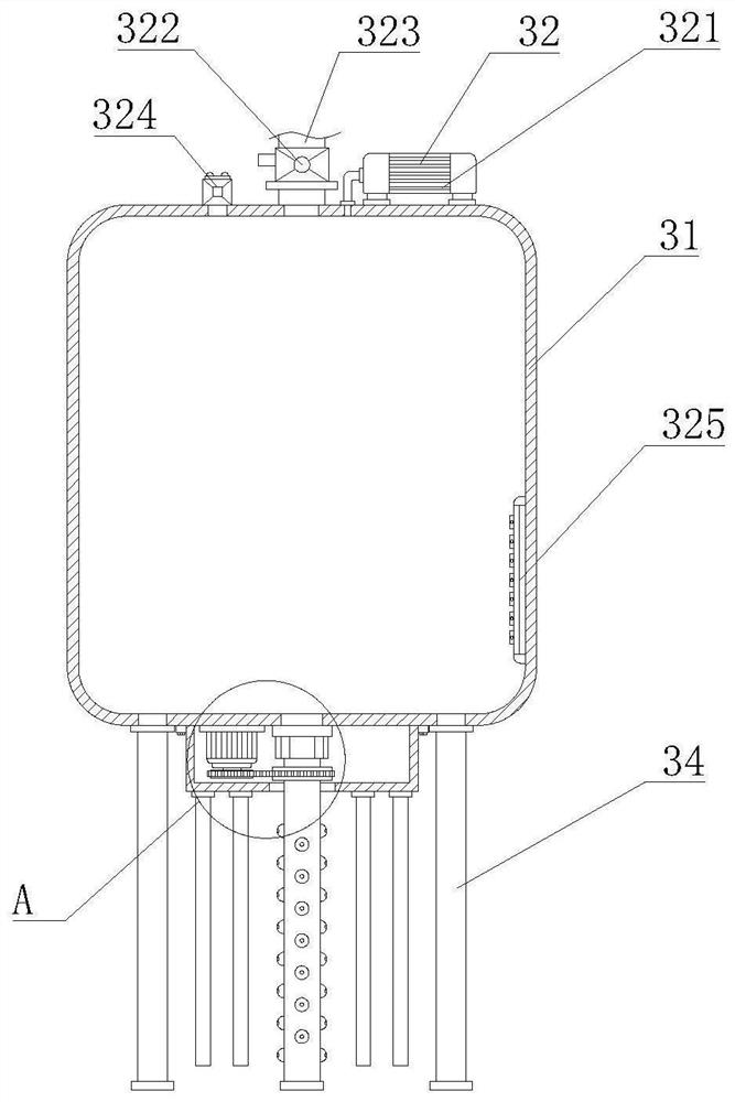
[0041]The uniform wetting mechanism 3 includes a sealing tank 31, the sealing tank 31 is fixedly installed on the top of the support 2, the top of the sealing tank 31 is provided with a power mechanism 32, the bottom of the sealing tank 31 is provided with a central wetting mechanism 33, and the bottom of the sealing tank 31 There are side wetting mechanisms 34 located on both sides of the central wetting mechanism 33, the power mechanism 32 includes an air pump 321, and the air pump 321 is fixedly installed on the top of the airtight tank 31, and the output end of the air pump 321 is fixedly connected to the top of ...
Embodiment 2
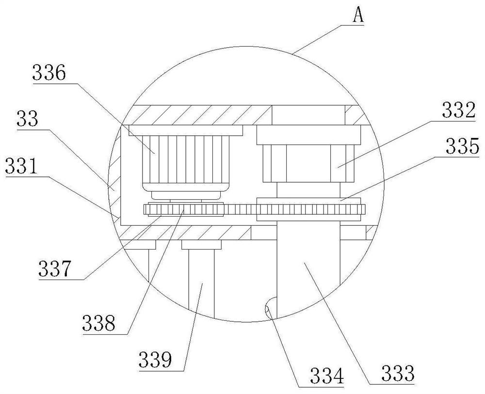
[0046] Such as Figure 1-7 As shown, on the basis of Embodiment 1, the present invention provides a technical solution: preferably, the top of the sealed tank 31 is fixedly connected with a water inlet solenoid valve 322 on the left side of the air pump 321, and the top of the water inlet solenoid valve 322 is fixedly connected to There is a water source connection pipe 323, the top of the sealed tank 31 is fixedly connected with a pressure relief solenoid valve 324 located on the left side of the water inlet solenoid valve 322, a water level sensor 325 is fixedly installed on the right side of the inner cavity of the sealed tank 31, and the inner cavity of the control box 331 The top is provided with the drive motor 336 that is positioned at the left side of rotary joint 332, and the output shaft of drive motor 336 is fixedly connected with drive gear 337, and the outer wall of drive gear 337 is meshed with drive chain 338, and drive chain 338 is away from one end of drive gea...
Embodiment 3
[0049] Such as Figure 1-7 As shown, on the basis of Embodiment 1, the present invention provides a technical solution: preferably, the side wetting mechanism 34 includes a wetting side plate 341, and the wetting side plate 341 is fixedly installed on the bottom of the airtight tank 31 to wet The front and back of the side plate 341 are fixedly equipped with mounting blocks 342, and the top of the wet side plate 341 is provided with a connection port 343, and the top of the connection port 343 is fixedly connected with the bottom of the airtight tank 31, and the right side of the wet side plate 341 A side plate water spray mechanism 344 is provided, and the side plate water spray mechanism 344 includes a water outlet pipe 3441, and the water outlet pipe 3441 is fixedly connected to the right side of the wetting side plate 341, and a diverter ring is fixedly installed on the right side of the inner cavity of the wetting side plate 341 3442, the center of the right side of the d...
PUM
 Abstract
Description
Claims
Application Information
 - R&D
- Intellectual Property
- Life Sciences
- Materials
- Tech Scout
- Unparalleled Data Quality
- Higher Quality Content
- 60% Fewer Hallucinations
Browse by: Latest US Patents, China's latest patents, Technical Efficacy Thesaurus, Application Domain, Technology Topic, Popular Technical Reports.
© 2025 PatSnap. All rights reserved.Legal|Privacy policy|Modern Slavery Act Transparency Statement|Sitemap|About US| Contact US: help@patsnap.com


