Soil-rock interbed embankment structure and design method thereof

A design method and rock interbed technology, applied in the field of soil-rock interbed embankment structure and its design, can solve problems such as difficult control of soil-rock interbed foundation settlement, inapplicable settlement calculation, difficult calculation of soil-rock interbed foundation settlement, etc. , to achieve the effects of stability in use, less construction tasks, and light weight

Active Publication Date: 2021-08-06
CHINA RAILWAY ERYUAN ENG GRP CO LTD
View PDF13 Cites 2 Cited by
  • Summary
  • Abstract
  • Description
  • Claims
  • Application Information

AI Technical Summary

Problems solved by technology

[0004] The purpose of the present invention is to provide a soil-rock interbed embankment structure in view of the problem that the newly built embankment will cause the subsidence of the soil-rock interbed foundation to be difficult to control when building an embankment on the soil-rock interbed in the prior art;
[0005] Aiming at the problem that the traditional settlement deformation design method is not suitable for the settlement calculation when building embankments on soil-rock interbed foundations, and it is difficult to calculate the settlement of soil-rock interbed foundations, a design method for soil-rock interbed embankment structures is provided

Method used


Image

  • Soil-rock interbed embankment structure and design method thereof
  • Soil-rock interbed embankment structure and design method thereof
  • Soil-rock interbed embankment structure and design method thereof

Examples


Embodiment 1

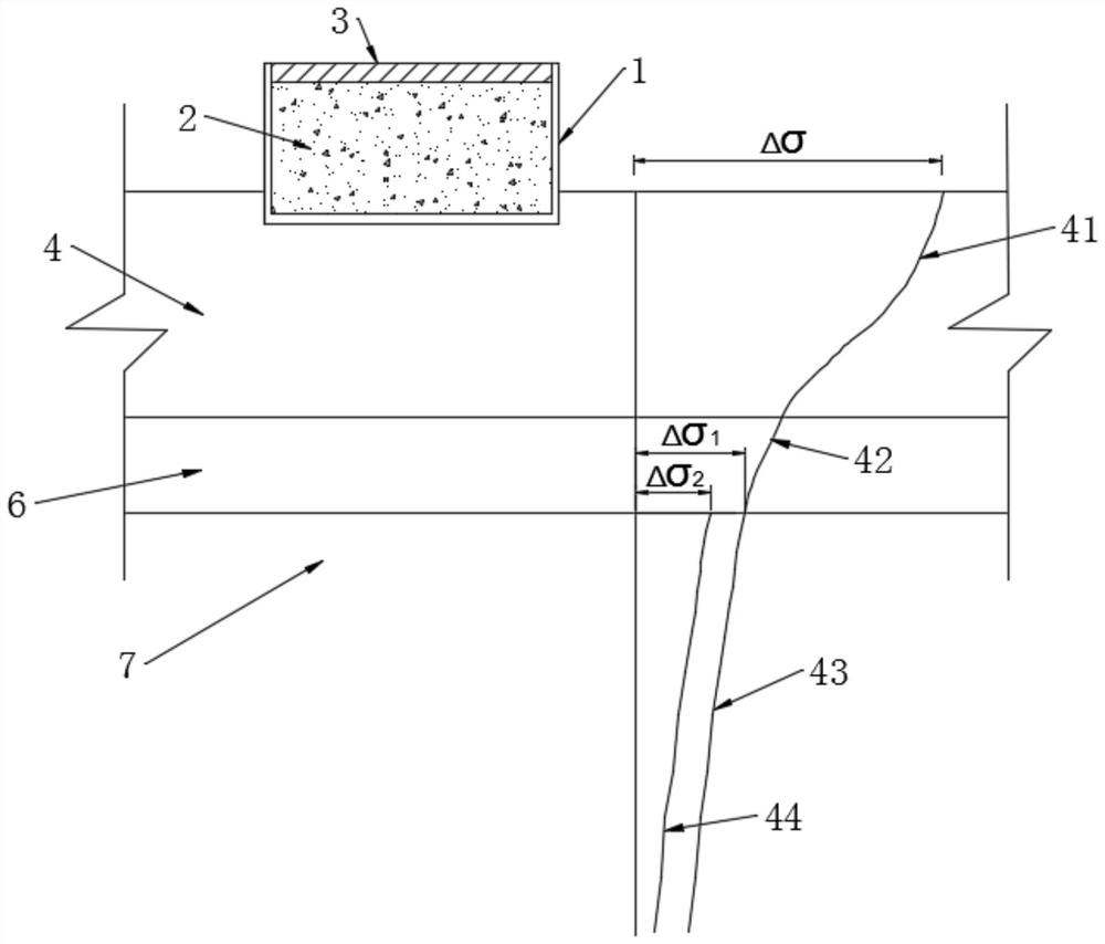
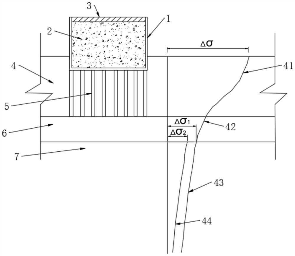
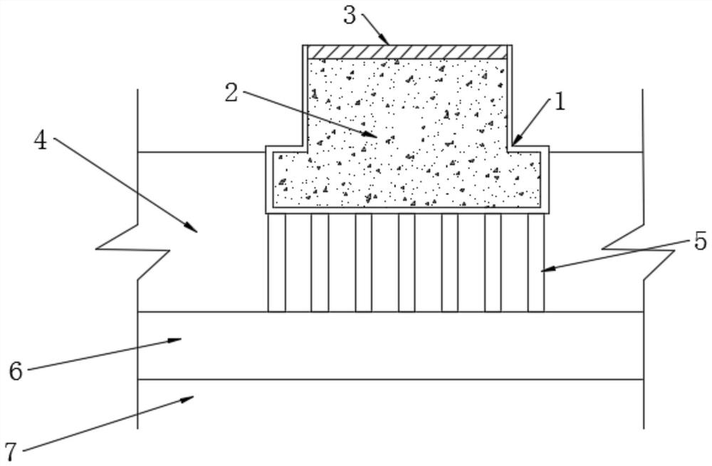
[0061] This embodiment provides a soil-rock interbedded embankment structure, see Figure 1-3 , located on the soil-rock interbed foundation, the soil-rock interbed foundation includes the first soil layer foundation 4, the rock layer 6 and the second soil layer foundation 7 from top to bottom; the soil-rock interbed embankment structure includes channel members 1. The opening of the channel member 1 faces upward, and the bottom of the channel member 1 is placed on the surface of the first soil layer foundation 4 or in the first soil layer foundation 4, and the inside of the channel member 1 is from The lightweight concrete layer 2 and the surface structure 3 are filled sequentially from bottom to top, and the surface structure 3 is used to protect the lightweight concrete layer 2 .

[0062] The channel member 1, the lightweight concrete layer 2 and the surface structure 3 are all arranged longitudinally along the road, and the two sides of the surface structure 3 are respecti...

Embodiment 2

[0067] This embodiment provides a design method of the soil-rock interlayer embankment structure as described in Embodiment 1. The soil-rock interlayer includes the first soil layer foundation 4, the rock layer 6 and the second soil layer foundation from top to bottom 7;

[0068] Also includes the following steps:

[0069] A. Obtain the thickness d of rock layer 6 through numerical simulation and field test 2 To the thickness influence coefficient ζ of additional stress, obtain the fragmentation degree influence coefficient η of the degree of fragmentation of the additional stress to the degree of fragmentation of the rock layer 6;

[0070] In step A, in the process of numerical simulation and field test, control the thickness of rock layer 6 or control the fragmentation degree of rock layer 6, and make statistics: the additional stress at the top of the second soil layer foundation 7 under the influence of no rock layer 6, with The additional stress on the top of the second...


PUM


Abstract

The invention provides a soil-rock interbed embankment structure and a design method thereof. The soil-rock interbed embankment structure is arranged on a soil-rock interbed foundation, and the soil-rock interbed foundation comprises a first soil layer foundation, a rock layer and a second soil layer foundation from top to bottom; the soil-rock interbed embankment structure comprises a groove-shaped component, an opening of the groove-shaped component faces upwards, the bottom of the groove-shaped component is arranged on a surface of the first soil layer foundation or in the first soil layer foundation, and the groove-shaped component is sequentially filled with a lightweight concrete layer and a surface layer structure from bottom to top; ad the surface layer structure is used for protecting the lightweight concrete layer. The structure is simple, only the first soil layer foundation needs to be constructed, control over settlement of the soil-rock interbed foundation can be met, the excavation amount is small, construction is convenient, the construction period can be shortened, construction cost can be saved, and settlement of the foundation can be better reduced.

Description

technical field [0001] The invention relates to the technical field of embankment construction, in particular to an earth-rock interbedded embankment structure and a design method thereof. Background technique [0002] When building high-speed railways in volcanic eruption areas, we often encounter soil-rock interbedded foundations. Soil-rock interbedded foundations refer to soil-layer foundations, rock layers, and soil-layer foundations from top to bottom. This staggered soil Interbedded rock foundations are formed by long-term accumulation of volcanic eruptions in different time periods. When building a ballastless track high-speed railway embankment project on this soil-rock interlayer foundation, what measures to use to reinforce the soil foundation and how to design the foundation settlement deformation are two major technical problems that need to be solved. Under such soil-rock interbedded foundation conditions, it is difficult for traditional composite foundation re...

Claims


Application Information

Patent Timeline
Patent Type & Authority Applications(China)
IPC IPC(8): E01B2/00E01B1/00E02D27/14G06F30/13
CPCE01B2/00E01B2/006E01B1/00E02D27/14G06F30/13
Inventor 姚裕春谢毅罗照新周成袁志刚封志军吴沛沛李宁张东卿袁碧玉
Owner CHINA RAILWAY ERYUAN ENG GRP CO LTD
Why Eureka
Try Eureka