Renewable energy green building system

A renewable energy and green building technology, applied in the field of construction, can solve the problems of large area occupied by walls, non-compliance with the concept of sustainable development, waste of space, etc., and achieve the effects of saving electric energy, convenient operation, and water resources

Pending Publication Date: 2021-08-06
杞梓林生态建设有限公司
View PDF6 Cites 0 Cited by
  • Summary
  • Abstract
  • Description
  • Claims
  • Application Information

AI Technical Summary

Problems solved by technology

[0004] Aiming at the deficiencies in the existing technology, the purpose of the present invention is to provide a renewable energy green building system, which solves the problem that the traditional wall occupies a large area and only acts as a barrier, resulting in waste of space. Problems that do not conform to the concept of development and the concept of sustainable development

Method used


Image

  • Renewable energy green building system
  • Renewable energy green building system
  • Renewable energy green building system

Examples


Embodiment 1

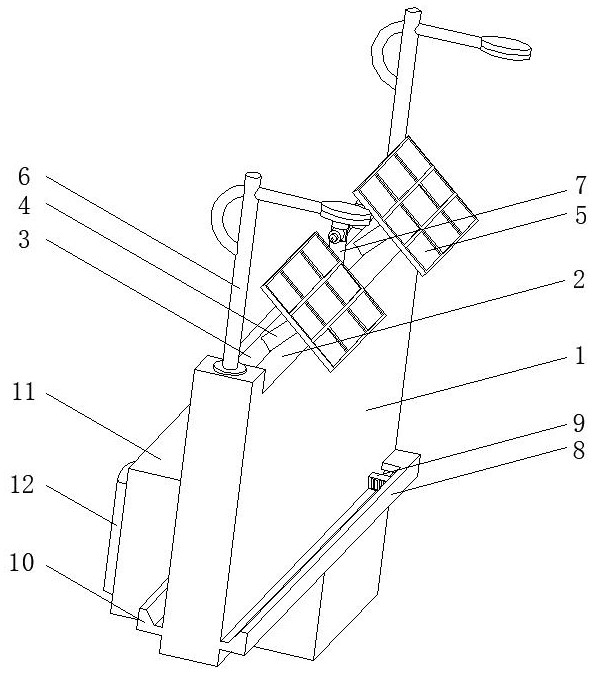
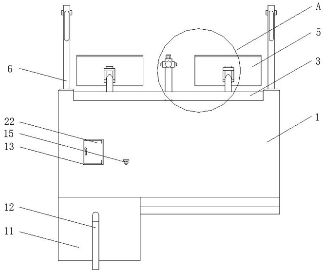
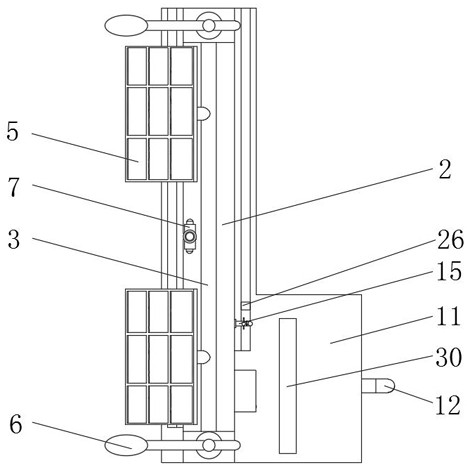
[0026] see Figure 1-6 , the present invention provides a technical solution: a renewable energy green building system, including a wall 1, a groove 2 is opened on the top of the wall 1, and the inner side of the groove 2 is movably connected with a connecting rotating rod 3, and the connecting rotating rod 3 The left and right ends extend to the inside of the fence 1, and the upper surface of the connecting rod 3 is fixedly connected with a group of left and right symmetrical support rods 4 by welding. A street lamp 6 is fixedly connected, a cleaning spray device 7 is fixedly connected to the middle position of the bottom end of the groove 2, a drainage groove-8 is fixedly connected to the lower side of the front end of the enclosure wall 1, and a filter plate-1 is fixedly connected to the inner rear side of the drainage groove-8. 9. The size and shape of the filter plate one 9 is compatible with the groove of the drainage groove one 8, the lower side of the rear end of the e...

Embodiment 2

[0029] Such as Figure 1-6 As shown, on the basis of Embodiment 1, the present invention provides a technical solution: the rear end of the solar panel 5 is fixedly connected with a connection block 16, the connection block 16 is U-shaped, and the top end of the support rod 4 is fixedly connected with a bolt 17, And the bolt 17 is horizontally fixedly connected to the top of the support rod 4, the bolt 17 runs through the connection block 16 transversely, the solar panel 5 forms a rotating structure through the connection block 16 and the bolt 17, and the top of the support rod 4 is located at the inside of the connection block 16.

[0030]In this embodiment, by manually pulling the connection block 16 to swing left and right on the bolt 17, the angle of the solar panel 5 is adjusted to the left and right through the swing angle, so that the solar panel 5 faces the sun, which is conducive to increasing the solar panel 5 sunlight exposure time, ensuring Convert more electrical ...

Embodiment 3

[0032] Such as Figure 1-6 As shown, on the basis of Embodiment 1 and Embodiment 2, the present invention provides a technical solution: the left and right ends of the connecting rod 3 are movably connected to the inside of the wall 1 through bearings, and the left side of the top inside of the wall 1 is movably connected Gear one 18 is arranged, and the left end that connects rotating bar 3 is fixedly connected with gear one 18, and the inner left side of wall 1 is movably connected with drive shaft 19, and drive shaft 19 is vertically movably connected in the inside of wall 1, and the top of drive shaft 19 is fixed Gear two 20 is connected, and the lower end of transmission shaft 19 is fixedly connected with gear three 21. Gear one 18 and gear two 20 form a meshing structure. The outside of control box 13 is movably connected with box door 22 through a hinge. The inner bottom of control box 13 The terminal is fixedly connected to the motor 24, the output end of the motor 24 ...


PUM


Abstract

The invention discloses a renewable energy green building system. The renewable energy green building system comprises an enclosing wall, a groove is formed in a top end of the enclosing wall, a connecting rotating rod is movably connected to an inner side of the groove, a left end and a right end of the connecting rotating rod extend into the enclosing wall, an upper surface of the connecting rotating rod is fixedly connected with a set of supporting rods in bilateral symmetry through welding, top ends of the supporting rods are movably connected with solar panels, and a left side and a right side of a top end of the enclosing wall are fixedly connected with street lamps correspondingly. The arranged solar panels are conductive for converting solar energy into electric energy to provide power for all electric devices, save electric energy, reduce pollution and meet a sustainable development environment protection concept, and renewable resources are utilized. A motor and the connecting rotating rod are connected in a transmission manner, front and back directions of the solar panels are adjusted by driving electric rods by the motors, and U-shaped connecting blocks and screw rods are arranged, and a left-right orientation of the solar panels can be conveniently adjusted.

Description

technical field [0001] The invention belongs to the technical field of buildings, and in particular relates to a renewable energy green building system. Background technique [0002] Construction refers to the assets made by man-made construction, which belongs to the category of fixed assets, including two categories of houses and structures. [0003] The fence belongs to the structure. The fence is widely used in modern society. The traditional fence is made of some wooden fences or earth and rocks, which makes the traditional fence occupy a large area and only plays a role of barrier, resulting in waste of space. The concept It is inconsistent with the concept of green development and sustainable development proposed by modern society. Contents of the invention [0004] Aiming at the deficiencies in the existing technology, the purpose of the present invention is to provide a renewable energy green building system, which solves the problem that the traditional wall occ...

Claims


Application Information

Patent Timeline
Patent Type & Authority Applications(China)
IPC IPC(8): E04H17/14E03B3/02E03F5/10B08B3/02H02S20/30H02S40/10
CPCE04H17/14E03B3/02E03F5/10B08B3/02H02S20/30H02S40/10Y02A20/108Y02E10/50Y02B10/10
Inventor 陈梦露林玲芝肖建茜戴梅涵陈煌刘泽斌
Owner 杞梓林生态建设有限公司
Why Eureka
Try Eureka