
Numerical control machine tool noise reduction protective door

A technology of CNC machine tools and protective doors, which is applied in the field of CNC machine tools, can solve the problems of inconvenient use and large space occupation of CNC machine tools, and achieve the effects of reducing noise emission, enhancing cleaning, and increasing speed

Active Publication Date: 2021-08-06
HANGZHOU VOCATIONAL & TECHN COLLEGE
View PDF6 Cites 0 Cited by
  • Summary
  • Abstract
  • Description
  • Claims
  • Application Information

AI Technical Summary

Problems solved by technology

[0005] In order to make up for the deficiencies of the existing technology, the protective door of the CNC machine tool is generally set by pulling it open or pushing it to both sides, but this setting method of the protective door takes up a lot of space, and it is necessary to leave enough opening for the protective door Space, for the inconvenient use of some smaller or smaller CNC machine tools, the invention proposes a noise reduction protective door for CNC machine tools

Method used


Image

  • Numerical control machine tool noise reduction protective door
  • Numerical control machine tool noise reduction protective door
  • Numerical control machine tool noise reduction protective door

Examples


Embodiment 1

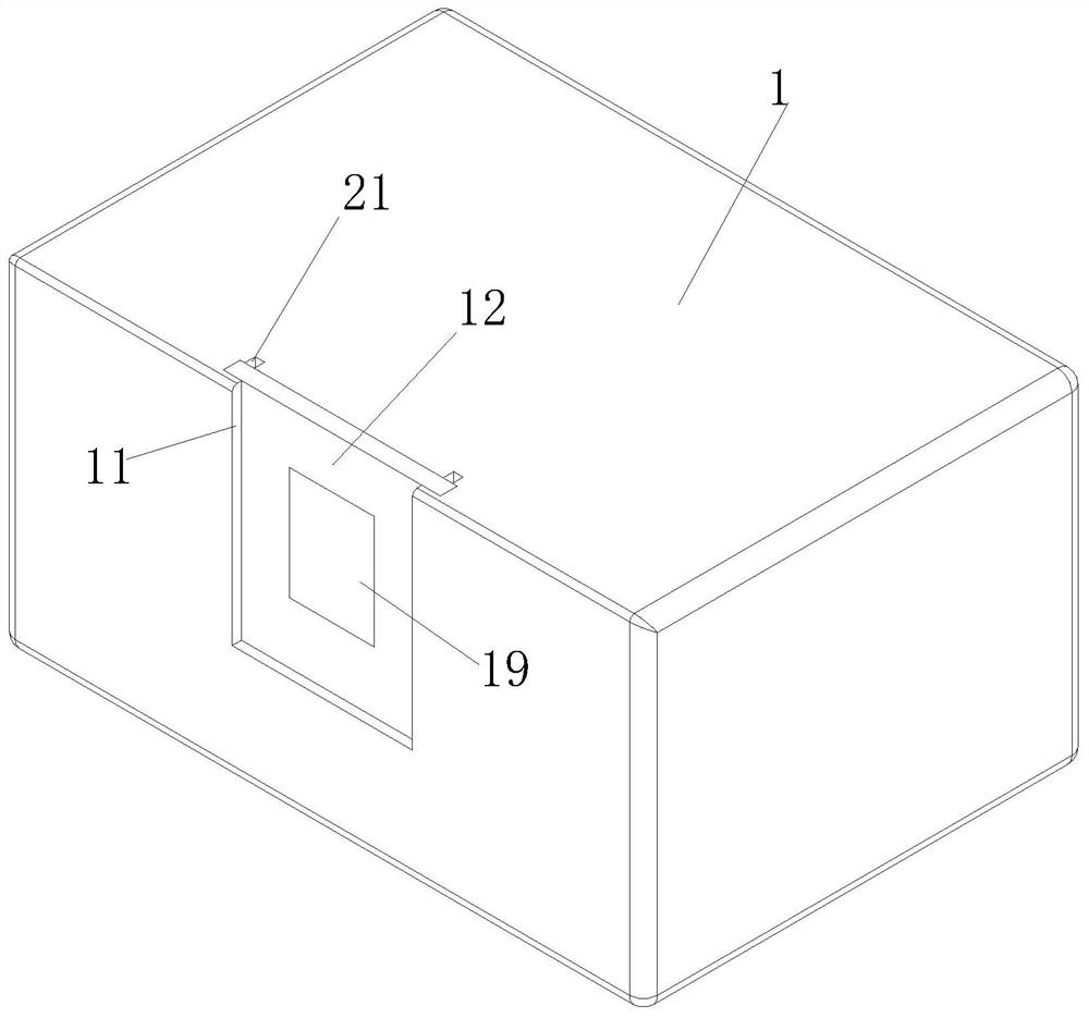
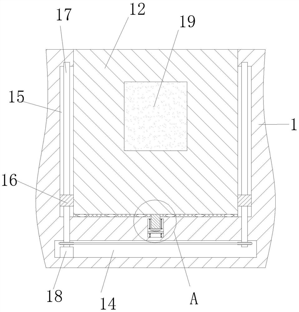
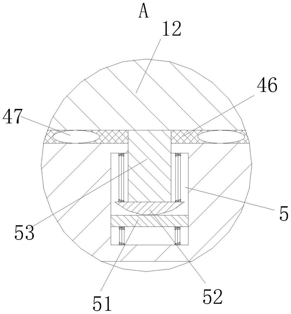
[0033] Such as Figure 1 to Figure 8 As shown, a kind of numerical control machine tool noise reduction protection door described in the present invention comprises a bed 1; the side wall of the bed 1 is provided with a door slot 11, and the side wall of the door slot 11 is provided with a surrounding slot 13; A protective door 12 is slidably connected to the surrounding groove 13; an observation window 19 is provided on the protective door 12, and double-layer glass is fixed in the observation window 19; a first cavity 14 is opened in the bottom of the surrounding groove 13 , and the groove bottom on both sides of the surrounding groove 13 is provided with a first groove 15; the top side wall of the first groove 15 is rotatably connected with a lead screw 17, and the bottom end of the lead screw 17 extends into the first cavity 14 , and the lead screw 17 stretches into the bar of the first cavity 14 and is fixedly connected with a sprocket; between the sprockets, it is driven...

Embodiment 2

[0043] see Figure 9 As shown in Comparative Example 1, as another embodiment of the present invention, a collection box 41 is affixed to the bottom end of the arc-shaped plate 4; during operation, a collection box 41 is affixed to the bottom end of the arc-shaped plate 4, The impurities thrown off from the cleaning wheel 2 and the impurities cleaned by the cleaning brush 45 will enter the collection chamber through the arc plate 4 .

[0044] Working principle: When it is necessary to open the CNC machine tool to place the product, start the motor 18, the motor 18 rotates through the sprocket and at the same time drives the screw 17 to rotate forward, and the forward rotation of the screw 17 will drive the moving block 16 to move upward in the first groove 15 , the moving block 16 moves to drive the protective door 12 upwards, and the protective door 12 is opened upwards. After the product is put into the bed 1, the motor 18 is turned to drive the lead screw 17 to reverse, and...


PUM


Abstract

The invention belongs to the technical field of numerical control machine tools, and particularly relates to a numerical control machine tool noise reduction protective door. The numerical control machine tool noise reduction protective door comprises a machine tool body. A door groove is formed in the side wall of the lathe bed, and a surrounding groove is formed in the side wall of the door groove; a protective door is slidably connected to the surrounding groove; an observation window is formed in the protective door, and double-layer glass is fixedly connected into the observation window; a first cavity is formed in the groove bottom of the surrounding groove, and first grooves are formed in the groove bottoms of the two sides of the surrounding groove; and lead screws are rotationally connected to the side walls of the top ends of the first grooves, the bottom ends of the lead screws extend into the first cavity, and chain wheels are fixedly connected to the parts, extending into the first cavity, of the lead screws. According to the numerical control machine tool noise reduction protective door, the problems that the protective door of the numerical control machine tool is generally pulled open or pushed to two sides, but the arrangement mode of the protective door occupies a large space, enough opening space needs to be reserved for the protective door, some small-sized or small-working-space numerical control machine tools are inconvenient to use are solved.

Description

technical field [0001] The invention belongs to the technical field of numerical control machine tools, in particular to a noise-reduction protection door for numerical control machine tools. Background technique [0002] CNC machine tool is an automatic machine tool equipped with a program control system. Compared with traditional machine tools, CNC machine tools have the advantages of high flexibility, high processing precision, and high productivity. Variety of parts processing problems. [0003] There are also some technical solutions about CNC machine tool technology in the prior art. For example, a Chinese patent with application number 2018110742186 discloses a protective door for CNC machine tools, including a fence, a protective door and a fingerprint recognition device. The fence There is a rectangular cavity in the middle of the plate, and sliding bars are symmetrically arranged on the upper and lower sides of the rectangular cavity. The protective door is symmet...

Claims


Application Information

Patent Timeline
IPC IPC(8): E06B5/10E05F15/665E06B5/20E06B7/28E06B7/30B23Q11/08
CPCE06B5/10E06B5/20E06B7/28E06B7/30E05F15/665B23Q11/08
Inventor 方映高庆云王惠姣张素颖凌华伟
Owner HANGZHOU VOCATIONAL & TECHN COLLEGE
Learn More