Eureka AIR delivers breakthrough ideas for toughest innovation challenges, trusted by R&D personnel around the world.

Riding law mower

A lawn mower, sitting technology, used in lawn mowers, harvesters, cutters, etc., can solve problems such as burning dry cuttings

Pending Publication Date: 2021-08-06
ANDREAS STIHL AG & CO KG
View PDF0 Cites 0 Cited by
  • Summary
  • Abstract
  • Description
  • Claims
  • Application Information

AI Technical Summary

Problems solved by technology

If the hot muffler housing comes into contact with e.g. dry cuttings, there is a danger of the dry cuttings being ignited due to the extreme heat of the muffler housing

Method used


Image

  • Riding law mower
  • Riding law mower
  • Riding law mower

Examples


Embodiment Construction

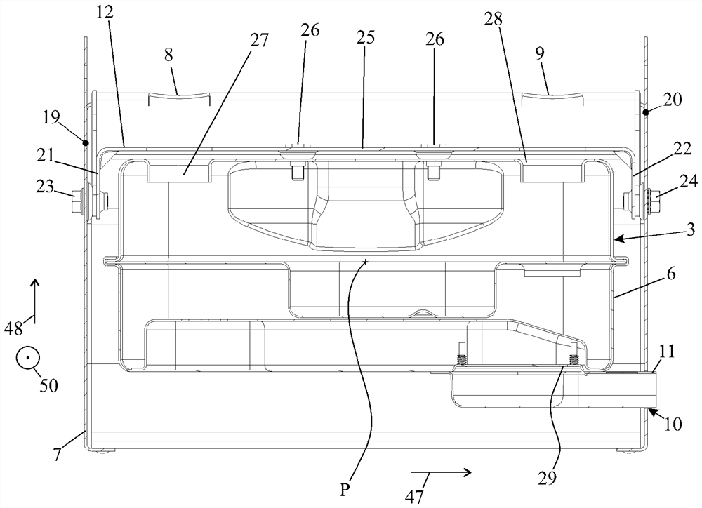
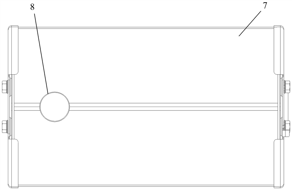
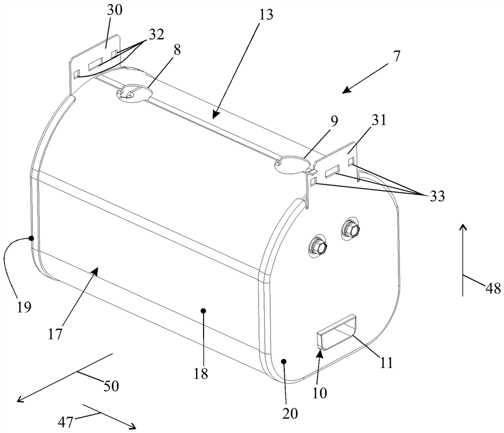
[0029] figure 1 A sit-down lawnmower 1 is shown. The sitting lawn mower 1 includes front wheels 41 . The front wheels 41 can be steered by means of a steering wheel 42 . When the sit-on lawn mower 1 is traveling straight, the sit-on lawn mower 1 travels in the direction of travel 50 . The direction of travel 50 extends in the direction of the longitudinal center axis 46 of the sit-on lawn mower 1 . When the sit-on lawnmower 1 is traveling straight ahead, the front wheels 41 rotate about a common axis of rotation 49 . The axis of rotation 49 runs perpendicular to the longitudinal center axis 46 . Arranged upstream of the axis of rotation 49 in the direction of travel 50 is the muffler 3 enclosed in the second housing 7 . The sound absorber 3 is arranged at the level of the axis of rotation 49 . The muffler 3 is in figure 1 Can't see it.

[0030] as in figure 2 As shown in , the muffler 3 is connected to the combustion motor 2 via a connecting line 4 . The muffler 3 -...


PUM


Abstract

The invention relates to a riding law mower. The riding lawn mower has an internal combustion engine (2) and a muffler (3) with a first housing (6). The internal combustion engine (2) is connected to the muffler (3) to supply exhaust gases originating to the first housing for noise damping. A second housing (7) is provided that thermally insulates the first housing (6). The second housing (7) at least partially encloses the first housing (6). The second housing (7) has an exterior side (15) with an emissivity of greater than 0.8, in particular, 0.9.

Description

technical field [0001] The present invention relates to a sitting lawn mower. Background technique [0002] Due to the exhaust gases introduced into the muffler, the housing of the muffler becomes very hot during operation. For sit-on lawn mowers, the muffler is usually arranged in front of the axle of the front wheels at the level of the axle. When the hot muffler housing comes into contact with, for example, dry cuttings, there is the risk of igniting the dry cuttings due to the extreme heat of the muffler housing. Contents of the invention [0003] The object of the present invention is to develop a sit-on lawn mower of the mentioned type in such a way that the risk of ignition from the sit-on lawn mower is reduced to a minimum. [0004] This object is solved by a sit-on lawnmower comprising a combustion motor and a muffler, wherein the combustion motor is connected to the muffler for guiding the exhaust gas, wherein the muffler has a first housing for muffler of the ...

Claims


Application Information

Patent Timeline
Patent Type & Authority Applications(China)
IPC IPC(8): F01N1/00F01N13/00F01N13/14F01N13/16F01N13/18A01D34/00A01D75/00A01D75/18A01D75/20
CPCF01N1/00F01N13/14F01N13/1805F01N13/1838F01N13/16F01N13/00A01D34/001A01D75/20A01D75/18A01D75/00F01N2260/20A01D2101/00F01N2590/00F01N13/002A01D34/826A01D34/71F01N13/141F01N2240/20F01N2530/06
Inventor W·路德维希C·罗尔莫瑟
Owner ANDREAS STIHL AG & CO KG
Why Eureka
Eureka Blog
Learn More