[0034] Next, the technical solutions in the embodiments of the present invention will be apparent from the embodiment of the present invention, and it is clearly described, and it is understood that the described embodiments are merely embodiments of the present invention, not all of the embodiments. Based on the embodiments of the present invention, there are all other embodiments obtained without making creative labor without making creative labor premises.
[0035] In order to make the above objects, features, and advantages of the present invention, the present invention will be further described in detail below with reference to the accompanying drawings and specific embodiments.
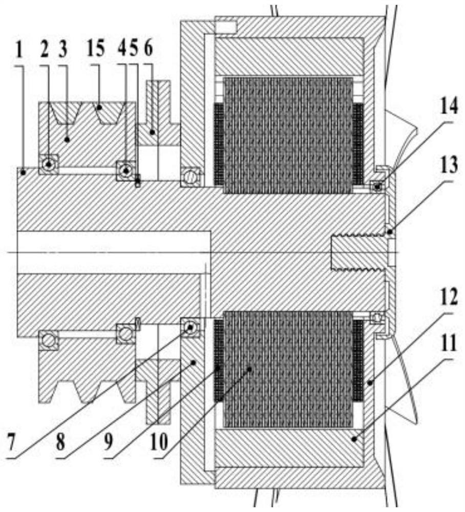
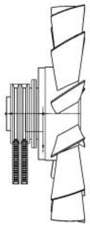
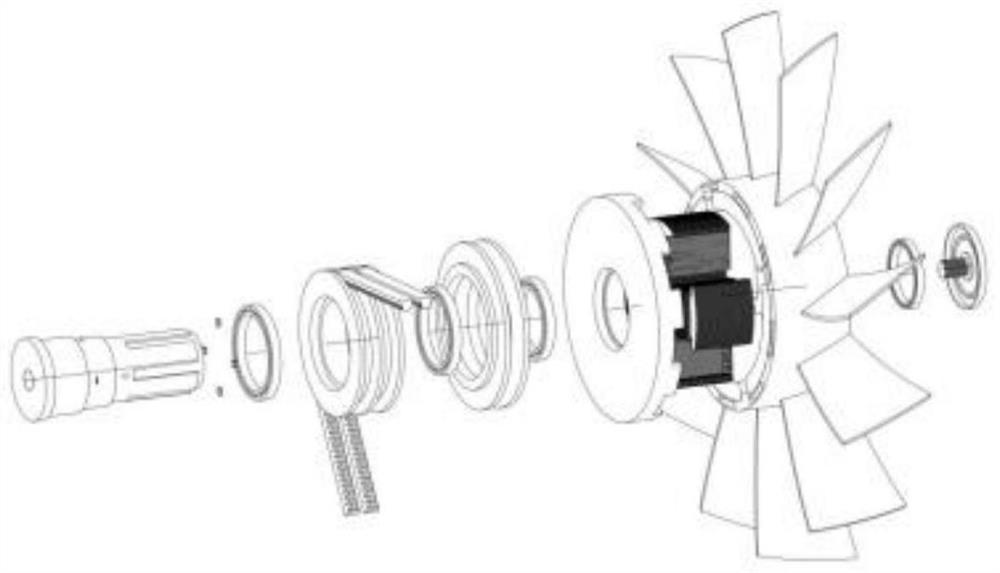
[0036] The present invention provides a diesel cooling fan having a driving source, for a diesel engine, including a spindle 1 mounted on a diesel engine; a spindle wheel 3, a clutch 6, a DC motor and a retreat Board 13; the outer wall of the DC motor is equipped with a cooling fan; both sides of the clutch 6 are directly transmitted from the belt wheel 3 and the cooling fan, respectively; the stopper plate 13 is threaded to the main shaft 1 away from the diesel engine.
[0037] The main shaft 1 is a penetrating spindle; the main shaft 1 is located at one end of the diesel engine to be positioned by the pulley first bearing 2; the bottom of the pulley 3 is fixed by the pulley second bearing 4 is fixed to the main shaft 1 outer edge shoulder; clutch 6 For power transmission or disconnection of the pulley 3 and the cooling fan.
[0038] In one embodiment of the invention, such as figure 1 The clutch 6 can be a surface-oriented structure of a symmetrical setting; when the pulley 3 is required to drive the driving cooling fan, the clutch 6 is driven; when the cooling fan is required to drive through a DC motor, the clutch 6 is disengaged, and the belt wheel 3 stops the drive.
[0039] The inner diameter of the pulley first bearing 2 is not smaller than the inner diameter of the pulley second bearing 4; the belt wheel second bearing 4 is close to the side of the clutch 6 is also provided with a retraction pin 5; the retaining pin 5 is interferring with the main shaft 1.
[0040] The cooling fan includes a sector 12 and a rear casing 8; the rear casing 8 is positioned on the main shaft 1 at the back shell bearing 7; the back cover 8 is rigidly connected to the clutch 6 side wall, and there is a number of spacings at the other end outer edge. A flower button;
[0041] The splined groove adapted to the spline is opened in the outer periphery, and the installation is adapted to the rear shell 8 by the spline groove; the sector is installed on the 12-week side of the sector. The sector bearing 14 of the sector 12; the stopper surface of the stopper plate 13 is adapted to the other side of the fan 12.
[0042] The DC motor includes a stator and a rotor; the stator is in-line with the spindle 1; the rotor is fitted in the inner wall of the sector 12; the sector 12 is rotated by the rotor.
[0043] The rotor includes a permanent magnet 11; the stator includes the armature core 10 and the armature winding 9; the armature core 10 is fixed to the spline of the spindle 1;
[0044] The spindle 1 is open to the blind hole; the main shaft 1 is attacked by the light pores of the blind hole; the power supply circuit of the armature winding 9 is placed in the blind hole.
[0045]An diesel cooled fan control method having a drive source, further comprising a water tank disposed on a cooling fan side; a diesel cooled fan control method includes:
[0046] Collection parameters: The parameters include the water tank temperature, the diesel temperature, the rotational speed, the clutch state, and the cooling fan speed;
[0047] The first working state: When the diesel engine is in a working condition, the cooling water temperature in the water tank is close to the ambient temperature, and it is determined that the diesel engine is a cold start state, the clutch is placed in a non-transmission state, the DC motor does not work, that is, cooling Fan does not work;
[0048] The second working state: When the diesel engine is in operation, it is in a high speed small load working condition, the cooling water temperature in the water tank is lower than the normal operating temperature, determines that the diesel engine is a cooling, and the clutch is placed in an unexposed state. The DC motor drives the cooling fan at a rotational speed below the pulley;
[0049] Third working state: When the diesel engine is in a working condition, the cooling water temperature in the water tank is higher than the normal operating temperature, and it is determined that the diesel engine is in the cooling state, then the clutch is placed in an unlike state, the DC motor is high. The cooling fan is driven to the speed of the pulley.
[0050] The cooling water temperature in the water tank is used to determine the working condition of the diesel engine; further comprising a fourth operating state: When the diesel engine is in a working condition, the cooling water temperature in the water tank is close to the normal operating temperature, and it is determined that the diesel engine is normal. The clutch is placed in a drive state, and the DC motor does not work. That is, the cooling fan is driven by the lens.
[0051] Also included in the fifth working state: When the diesel engine is in a brake state, the clutch is placed in an unlike state. The reduction in the speed of the diesel engine will decrease the speed of the belt pulley, that is, the moment of rotation of the cooling fan is lost.
[0052] In an embodiment of the invention, if figure 1 The pulley 3 is provided with a double belt 15.
[0053] In an embodiment of the invention, if Figure 4 In the motor speed control method, the DC motor speed can adopt a variety of forms including but not limited to linear functions, taking into account the limitations of vehicle microcontroller calculations and storage resources, optimization is linearly optimized by parameters. function. It can also be made into a three-dimensional MAP table for ECU interpolation query.
[0054] Further, the control strategy is performed by the fan control unit (FCU), and the engine control unit (ECU) is connected to the vehicle CAN network, and the current engine water temperature and the body temperature are queried from the ECU, and the variable input as the control function 2 is input. .
[0055] Further, it is necessary to indicate that the MAP table is the engine's professional term, hereby the fan speed data present in the fan control unit FCU of the present invention, and the data content is specifically a vehicle speed V, a diesel speed ω, a cooling water temperature T1 and a diesel engine body. Temperature T2 (ie, function independent variable) is mapped to a mathematical relationship of the cooling fan speed N (ie, the function variable).
[0056] More specifically, in an embodiment of the invention, the specific control strategy is as follows, such as Figure 5-7 , Including: variable definition: diesel engine water temperature T1; body temperature T2; diesel engine speed; vehicle speed V; diesel brake state FLAG1 (in diesel brake state); clutch state Flag2 (in a drive state); cooling fan speed N.
[0057] Constant definition: low cooling water temperature TA (slightly above ambient temperature); high cooling water temperature Tb (slightly higher than normal working water temperature); diesel engine idle speed ω1; diesel engine rated speed ω2.
[0058] Function1
[0059]
[0060] Note: 中 | Logic or symbol; && is logical and symbol.
[0061] The above expression is a clutch transmission control method, which should be pointed out that each constant in the expression and its neighboring radius are given by a particular diesel engine, and the strategy text is described below.
[0062] Clutch 6 disengaged conditions:
[0063] 1. When the diesel engine is at a high speed, the cooling water temperature is below the normal operating temperature, and the diesel engine is in a cooling state, then the clutch 6 is placed in the non-transmission state, and the fan is driven by a DC motor.
[0064] 2, when the cooling water temperature is close to the ambient temperature, it is determined that the diesel engine is in the cooler start state, in order to activate the diesel engine, the clutch 6 is placed in the non-transmission state.
[0065] 3. When the vehicle is in the diesel brake state, the heat dissipation fan will decelerate with the main shaft 1, resulting in a loss of the inertia of the rotation, so the clutch is not driven.
[0066] Clutch transmission conditions are:
[0067] 1. When the diesel machine cooling water temperature is at a high level and the medium and high load operation, the cooling fan consumption is smaller than the whole machine, so the pulley drives the cooling fan.
[0068] Function2
[0069]
[0070] The above expression is the motor speed control method, which should be pointed out that each parameter value in the expression should be given by a specific diesel engine, and the above policy text is described below.
[0071] 1. When the clutch 6 is in the transmission state, the DC motor is stopped, and the cooling fan is driven by a pulley; when the cooling water temperature is close to the ambient temperature, it is determined as a cold start state, the motor is stopped.
[0072] 2, when the clutch 6 is in the non-transmission state, the electrical flow speed speed is about the four-dimensional function of the vehicle speed, the diesel engine speed, the cooling water temperature and the temperature of the body, wherein the 2, η3, 4 is a positive parameter, that is, the cooling fan rotation and diesel engine The speed of the speed, cooling water temperature, body temperature is positively correlated; η1 is negative parameters, that is, when the vehicle speed is large, the wind will enhance the cooling of the diesel engine, so the cooling fan speed is negatively correlated with the vehicle speed.
[0073] The above test conditions will trigger all controls in the control strategy, it can be briefly: the diesel engine is started from the cold machine to the idle condition, accelerated to the rated operating point, and then decelerate the diesel brake to the stop; vehicle speed self-sport At the end of the condition, speed up to the maximum, slow down; the diesel engine temperature is gradually rising to normal working water after the diesel engine is started.
[0074] It should be noted that in order to realize the vehicle for diesel engine to park, this program assumes that the test vehicle adopts a stepless gearbox.
[0075] The control strategy will control the device as follows:
[0076] At 0-t1, the conditions T1∈U (Ta, δ) are true, the clutch 6 does not drive, the DC motor speed is 0; that is, the cooling fan does not rotate, so that the diesel engine is rapidly started and the heaters.
[0077] T1-T at time, the conditions ω∈u (ω1, δ) are true, the clutch 6 does not transpose; For true, the motor speed N = η1v + η2ω + η3t1 + η4t2. That is, the diesel engine is at a low speed load condition. At this time, the belt wheel drives the cooling fan will result in insufficient heat dissipation, so the motor drives the fan; so that the diesel power is fast.
[0078] At the time of T3-T4, the conditions T1∈U (Tb, δ) & Ω ∈U (ω2, δ) are true, clutch 6 transmission; condition FLAG1 = 1 is true, the motor speed is 0. That is, when the diesel engine is in a large load condition, the fan power is relatively small relative to the diesel output power, at which time the pulley 3 drives the fan on the diesel power and efficiency.
[0079] T4-T5 always, the conditions FLAG1 = 0 is true, the clutch is not transh; condition For true, the motor speed is n = η1V + η2ω + η3t1 + η4t2. That is, when the vehicle is decelerated from the high-speed state, when the clutch transmission is maintained, the fan will reduce the loss with the crankshaft, causing the moment of inertia. At this time, it is incorporated into the non-transmission state, and the cooling fan drive source is switched to a DC motor.
[0080] In the description of the present invention, it is to be understood that the term "longitudinal", "horizontal", "upper", "lower", "front", "post", "left", "right", "vertical", The orientation relationship between "horizontal", "top", "bottom", "inside", "outside", etc. is based on the orientation or positional relationship shown in the drawings, but is intended to facilitate the description of the present invention, not an indication or I suggest that the device or component must have a specific orientation, constructed and operated in a particular direction, and thus is not to be construed as limiting the invention.
[0081] The embodiments described above are merely described in the preferred embodiments of the present invention, and are not limited to the scope of the invention, and various articles of the present invention will have various techniques for the present invention without departing from the spirit of the invention. Deformation and improvement, should fall within the scope of protection determined by the claims of the present invention.