Efficient bearing ball mounting machine

A ball loader and bearing technology, applied in bearing components, shafts and bearings, mechanical equipment, etc., can solve the problems of height deviation between steel balls and cages, steel balls are not easy to enter the ballway, and bearing service life is reduced, etc. The effect of high rate, good quality of ball loading and long service life

Pending Publication Date: 2021-08-06
邢台郭工机械制造有限公司
View PDF0 Cites 0 Cited by
  • Summary
  • Abstract
  • Description
  • Claims
  • Application Information

AI Technical Summary

Problems solved by technology

[0002] The high-efficiency bearing ball loading machine in the prior art includes a ball loading basin, a rotatable distribution mold, a deck mold and a driving device for placing the cage, and the driving device is used to control the timing rotation of the material distribution mold and the deck mold. However, the timing control in the prior art only uses a time relay for simple control, which has poor stability, easy failure of control, and inaccurate control. If the deck mold cannot accurately stay in the position aligned with the fairway, There will be a height deviation between the steel ball and the cage, and the steel ball cannot be stuck into the cage even through the rotation of the splitting die, resulting in a greatly increased defective rate. Due to the need for manual adjustment, the work efficiency is greatly reduced
[0003] In the prior art, the ball lane of the splitting mold is only a passage suitable for the diameter of the steel ball, but when the steel ball enters the ball lane from the ball basin, the steel ball is not easy to enter the ball lane because the diameter difference between the ball lane and the steel ball is small , and when the steel ball is stuck into the cage from the cone corner, because it is relatively smooth and the friction force is not enough, the force when the steel ball is clipped into the cage is small, and it is easy to loosen after being clipped into the cage, which shortens the service life of the bearing. reduce
[0004] In the prior art, the devices used to drive the rotation of the splitting mold are all installed on the table, which is not only unsightly but also takes up space on the table, and has poor safety performance. It is easy to collect dust and damage when exposed to the external space

Method used


Image

  • Efficient bearing ball mounting machine
  • Efficient bearing ball mounting machine

Examples


Embodiment

[0025] Embodiment Efficient bearing ball loading machine

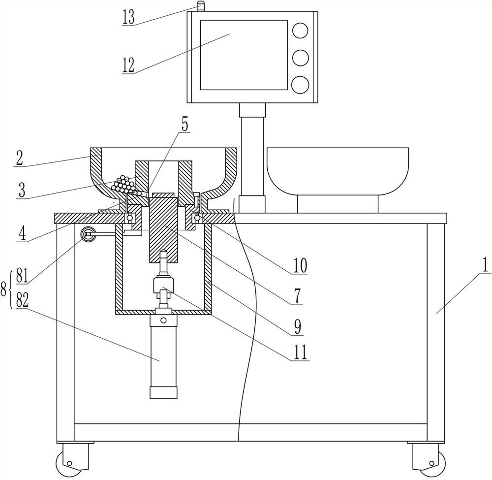
[0026] This example figure 1 , figure 2 As shown, a high-efficiency bearing ball loading machine includes a table body 1, a ball loading device and a control device arranged on the table body 1, the table body 1 is provided with a runner, and the ball loading device is provided with two , to form a double station, and the two ball loading devices are controlled by one control device, saving production costs.

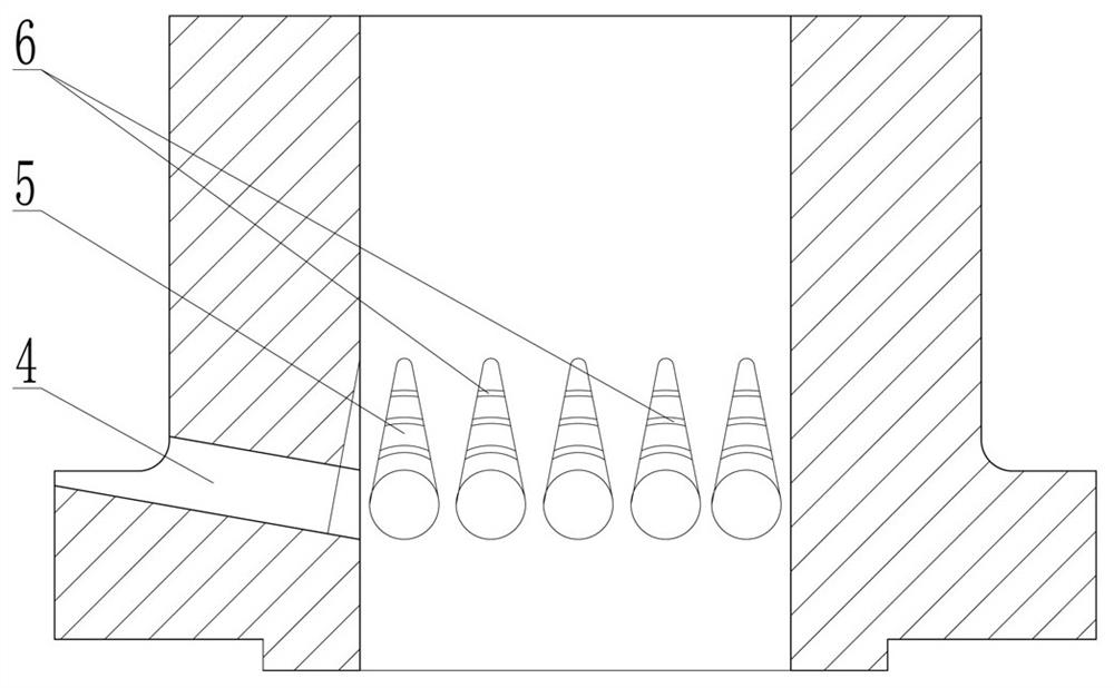
[0027] The ball loading device comprises a ball loading basin 2, a material distribution mold 3, a holder mold 7 and a driving device 8, and the ball loading basin 2 is fixed on the table top of the table body 1, and the inside of the ball loading basin 2 is Conical shape inclined towards the center, the center of the ball-loading basin 2 is provided with a circular hole for placing the distribution mold 3 .

[0028] The position corresponding to the round hole of the ball basin 2 on the table body 1 is provi...


PUM


Abstract

The invention discloses an efficient bearing ball mounting machine, and belongs to the technical field of bearing manufacturing. The efficient bearing ball mounting machine comprises a table, ball mounting devices and a control device. Each ball mounting device comprises a ball mounting basin, a distribution mold, a clamping seat mold and a driving device for enabling steel balls to enter a retainer, wherein a cavity for enabling the clamping seat mold to move up and down is formed in the distribution mold, ball grooves for the steel balls to enter the retainer from the ball mounting basin are obliquely formed in the outer circumference of the distribution mold, the end, communicated with the ball mounting basin, of each ball groove is in a horn mouth shape, the end, communicated with the cavity of the distribution mold, of each ball groove is provided with a taper angle part, and the face, in contact with the steel balls, of each taper angle part is provided with anti-slip lines. The driving device comprises a stroke air cylinder and an oscillation air cylinder. The control device comprises a touch screen and a PLC control module, and the PLC control module is electrically connected with the oscillation air cylinder and the stroke air cylinder. The efficient bearing ball mounting machine is high in ball mounting efficiency and good in ball mounting quality, the steel balls are not liable to loosen, the defective rate is low, control is sensitive and accurate, the safety performance is good, and the efficient bearing ball mounting machine is suitable for mounting steel balls in all bearings.

Description

technical field [0001] The invention belongs to the technical field of bearing production and relates to a high-efficiency bearing ball loading machine. Background technique [0002] The high-efficiency bearing ball loading machine in the prior art includes a ball loading basin, a rotatable distribution mold, a deck mold and a driving device for placing the cage, and the driving device is used to control the timing rotation of the material distribution mold and the deck mold. However, the timing control in the prior art only uses a time relay for simple control, which has poor stability, easy failure of control, and inaccurate control. If the deck mold cannot accurately stay in the position aligned with the fairway, There will be a height deviation between the steel ball and the cage, and the steel ball cannot be stuck into the cage even through the rotation of the splitting mold, resulting in a greatly increased defective rate. Due to the need for manual adjustment, the wor...

Claims


Application Information

Patent Timeline
Patent Type & Authority Applications(China)
IPC IPC(8): F16C43/06
CPCF16C43/065
Inventor 郭金锋
Owner 邢台郭工机械制造有限公司
Why Eureka
Try Eureka