
Design method of high-resolution large-view-field space optical remote sensor

A space optical remote sensing and design method technology, applied in optics, optical components, instruments, etc., can solve the problems of increasing load weight, power consumption, processing, testing, installation and adjustment, and time-consuming, etc., to reduce processing and manufacturing. Difficulty, improve the ability to collect information, improve the effect of image quality

Active Publication Date: 2021-08-06
BEIJING RES INST OF SPATIAL MECHANICAL & ELECTRICAL TECH
View PDF6 Cites 4 Cited by
  • Summary
  • Abstract
  • Description
  • Claims
  • Application Information

AI Technical Summary

Problems solved by technology

However, multiple remote sensors are required, which increases the weight and power consumption of the load. It is extremely difficult to guarantee the direct consistency of multiple remote sensors, and subsequent images have defects.
The scanning mirror / satellite sweep method uses on-orbit adjustment of the optical axis of the camera to increase the ground width, but the movement will reduce the reliability of the system. Time-sharing detection is required for targets in different areas, which greatly improves the detection ability of time-sensitive targets. reduce
The free-form surface optical design method adopts an asymmetric structure to improve the ability to balance off-axis aberrations, thereby significantly improving the field of view adaptability of the optical system. However, the free-form surface design is difficult to characterize, and the calculation is complicated and time-consuming. Processing, testing , It is difficult to install and adjust

Method used


Image

  • Design method of high-resolution large-view-field space optical remote sensor
  • Design method of high-resolution large-view-field space optical remote sensor
  • Design method of high-resolution large-view-field space optical remote sensor

Examples


Embodiment Construction

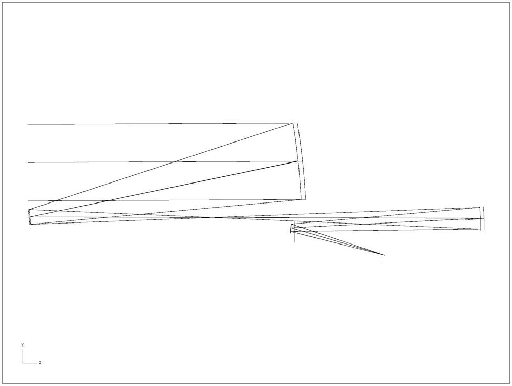
[0034] The realization flowchart of the method proposed by the present invention is as attached figure 1 shown. The specific description is as follows:

[0035] The optical system of the scene to be shot is designed to obtain a blurred image in the middle, and then through the image restoration algorithm, a clear scene image with high resolution and large field of view is obtained.

[0036] Among them, the optical system takes the point spread function consistency of each field of view as the design and optimization goal, which is different from the design method in the traditional design method that takes the best imaging quality as the design goal. The traditional optical design method obtains an optical imaging system with good middle image quality and poor edge image quality. In the consistency optimization design of the point spread function of each field of view, the consistency of the point spread function of each field of view is better, the imaging quality of the mi...


PUM


Abstract

The invention relates to a design method of a high-resolution large-view-field space optical remote sensor. The method comprises the steps of firstly, carrying out optimization design on an optical system by taking the consistency of point spread functions of each view field of a high-resolution large-view-field optical system as an optimization target of the optical system to obtain the optical system of which the point spread functions of each view field are approximately consistent; enabling a clear scenery image to pass through the designed optical system to obtain a uniform and blurred intermediate image in a view field, and improving the image quality of the image in the whole view field through a calculation restoration method. Due to the fact that the design difficulty of the high-resolution large-view-field space optical remote sensor is divided into a hardware implementation part and a software implementation part, the machining and manufacturing difficulty of hardware is lowered, and the design and manufacturing of the optical remote sensor with higher resolution and larger view field can be achieved through an existing machining method. As the consistency of the point spread functions of each view field is adopted as the optimization target of the optical system, the information collection capability of the optical system on an edge view field is improved, the difficulty of image restoration is reduced, and the quality of image restoration is improved.

Description

technical field [0001] The invention relates to a design method of a space optical remote sensor with high resolution and large field of view, which can be applied to the design of space optical remote sensor with high resolution and large field of view in my country, and realizes space optical remote sensing with higher resolution and larger field of view device design. Background technique [0002] High-resolution and large-field-of-view imaging is a technical challenge faced by aerospace optical remote sensors. It is difficult to achieve both with traditional design methods. The fundamental reason is: limited by the materials of optical components, high-resolution remote sensors generally use reflective optical systems . Reflective optical systems have limited aberration correction capabilities and poor off-axis aberration correction capabilities. Common methods to increase the field of view of remote sensors include the use of multi-lens field of view splicing, scanning...

Claims


Application Information

Patent Timeline
Patent Type & Authority Applications(China)
IPC IPC(8): G02B27/00G06T5/00
CPCG02B27/0012G06T2207/10032G06T5/77
Inventor 徐婧苏云俞越焦建超吕红韩潇王超葛婧菁张牧尧邵晓鹏席特立魏士杰
Owner BEIJING RES INST OF SPATIAL MECHANICAL & ELECTRICAL TECH
Learn More