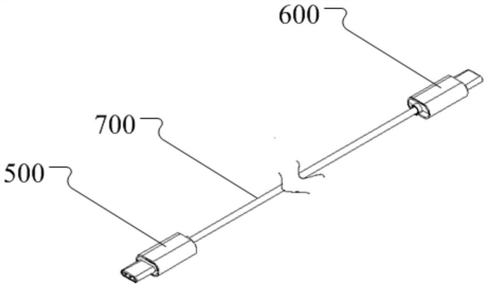
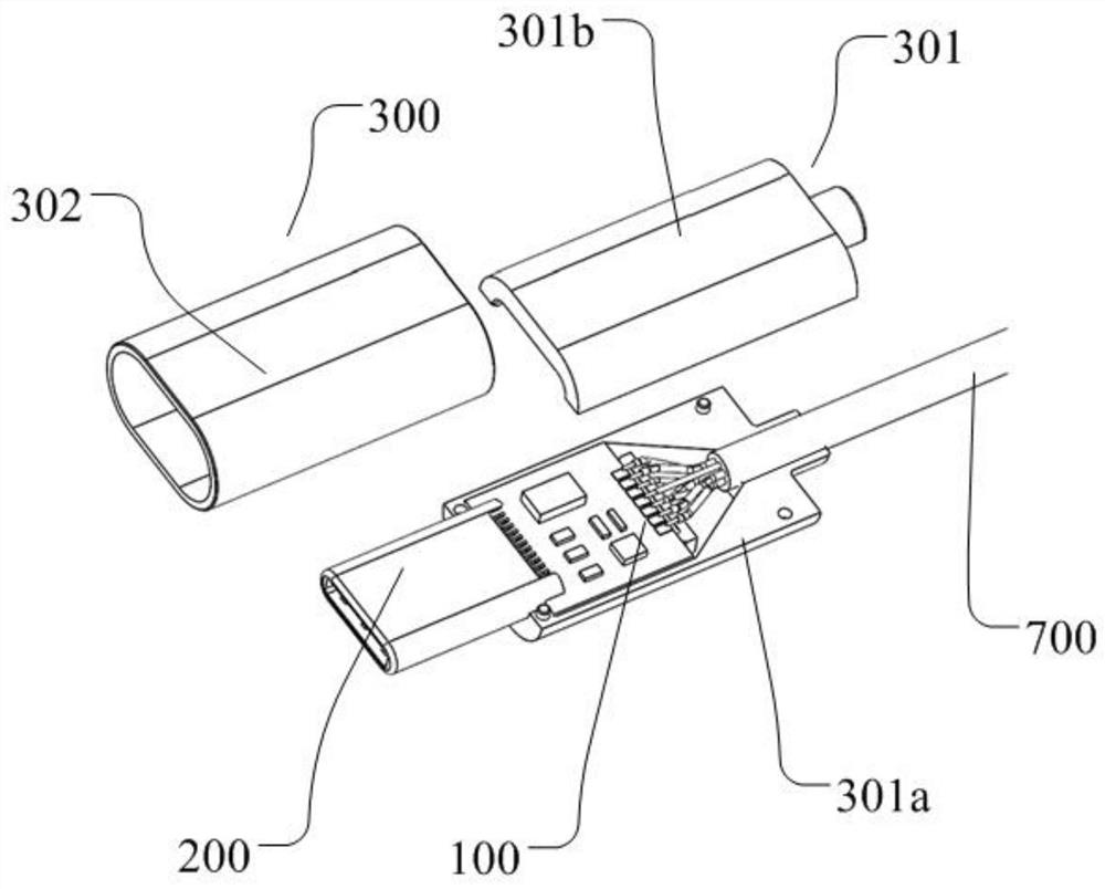
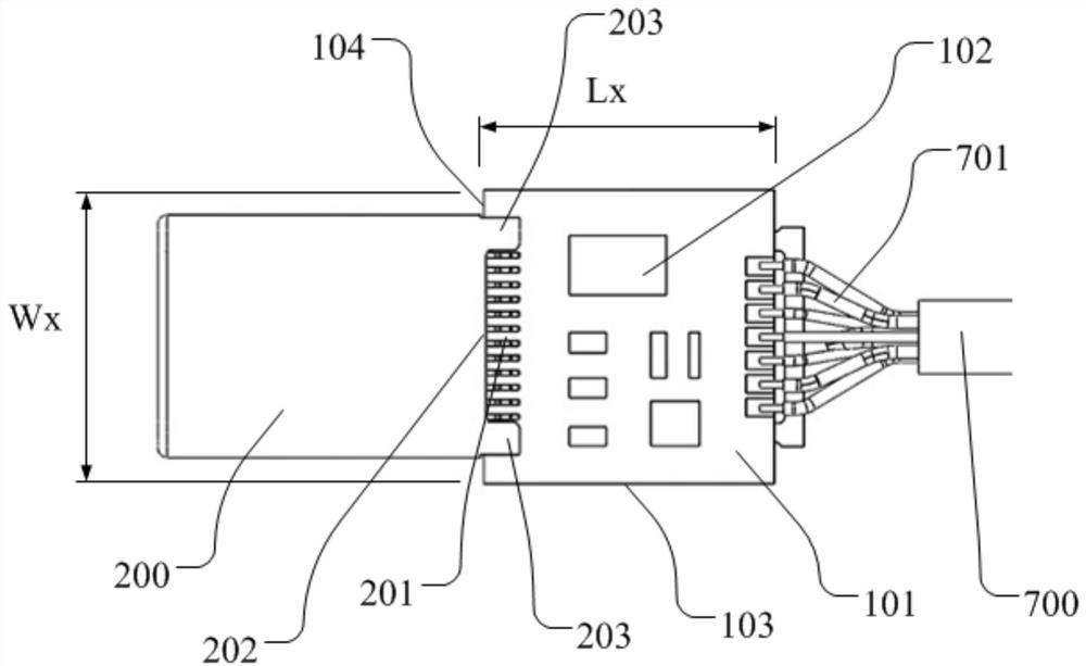
Shell structure of photoelectric module, connector, data line and manufacturing method

An optoelectronic connector and housing structure technology, which is applied in the direction of connection, coupling of optical waveguides, components of connecting devices, etc. The problem of large joint size, etc., achieves the effect of easy quality control, strong controllability, and high shell strength

Pending Publication Date: 2021-08-06
武汉钧恒科技有限公司
View PDF0 Cites 0 Cited by
  • Summary
  • Abstract
  • Description
  • Claims
  • Application Information

AI Technical Summary

Problems solved by technology

At present, various electrical connectors are used in electronic equipment to realize the connection of electrical signals, which cannot meet the data transmission requirements of VR and other equipment, or the connector joints are too bulky to carry
In addition, conventional methods such as integrated injection molding are used for the connection between the cable and the plug on the market. Its structure and assembly process will cause extrusion and deformation of the internal lens or components of the photoelectric module, and the outer shell is not suitable for the photoelectric module. to use, or not to use
Other methods are too large in size, unreliable in structure, high in processing and manufacturing costs, complex in assembly process, and have high requirements for operation control points

Method used


Image

  • Shell structure of photoelectric module, connector, data line and manufacturing method
  • Shell structure of photoelectric module, connector, data line and manufacturing method
  • Shell structure of photoelectric module, connector, data line and manufacturing method

Examples


Embodiment Construction

[0038] In order to make the object, technical solution and advantages of the present invention clearer, the present invention will be further described in detail below in conjunction with the accompanying drawings and embodiments. It should be understood that the specific embodiments described here are only used to explain the present invention, not to limit the present invention. In addition, the technical features involved in the various embodiments of the present invention described below can be combined with each other as long as they do not constitute a conflict with each other.

[0039] In describing the present invention, it should be understood that the terms "upper", "lower", "front", "rear", "left", "right", "vertical", "horizontal", "transverse", The orientations or positional relationships indicated by "longitudinal", "top", "bottom", "inner", "outer", and "circumferential" are based on the orientations or positional relationships shown in the drawings. The interp...


PUM


Abstract

The invention discloses a shell structure of a photoelectric module, a photoelectric connector, a data line and a manufacturing method of the data line. The shell structure comprises an inner shell and an outer shell, the inner shell comprises a first half shell and a second half shell, the inner shell formed by the first half shell and the second half shell is provided with a cavity, the first half shell and the second half shell are provided with fixing structures, the fixing structures are used for fixing the photoelectric module, and the outer shell is fixed outside the inner shell. According to the shell structure of the photoelectric module, the photoelectric connector and the manufacturing method of the photoelectric connector, the shell structure is simple, is high in strength, reliable in internal protection, low in processing cost and small in size; and the assembly process of the shell structure is simple, the controllability is high, and batch production is facilitated.

Description

technical field [0001] The invention relates to the field of optoelectronics, in particular to a housing structure of an optoelectronic module, an optoelectronic connector, a data line and a manufacturing method thereof. Background technique [0002] With the advent of 5G and the development of smart terminal devices, the requirements for data transmission are getting higher and higher. At present, various electrical connectors are used in electronic devices to realize the connection of electrical signals, which cannot meet the data transmission requirements of VR and other devices, or the connector joints are too bulky and inconvenient to carry. In addition, conventional methods such as integrated injection molding are used for the joints of cables and plugs on the market. Its structure and assembly process will cause extrusion and deformation of the internal lens or components of the photoelectric module, and the shell is not suitable for photoelectric modules. available,...

Claims


Application Information

Patent Timeline
Patent Type & Authority Applications(China)
IPC IPC(8): H01R31/06H01R13/502H01R13/66H01R43/20G02B6/42
CPCG02B6/4256G02B6/428H01R13/502H01R13/665H01R31/065H01R43/205
Inventor 蒋军金兴汇唐凌峰陈照华
Owner 武汉钧恒科技有限公司
Why Eureka
Try Eureka