
Valve clamping device

A valve and fitting technology, applied in the direction of heart valve, valve annulus, etc., can solve the problems of high surgical risk, large degree of stretching, and risk of splitting of the mitral valve leaflet, so as to reduce blood regurgitation, reduce The effect of little resistance

Pending Publication Date: 2021-08-10
GUANGDONG PULSE MEDICAL SCI & TECH CO LTD
View PDF6 Cites 3 Cited by
  • Summary
  • Abstract
  • Description
  • Claims
  • Application Information

AI Technical Summary

Problems solved by technology

[0005] Surgical treatment of mitral regurgitation has the disadvantages of many complications, long recovery period, and high surgical risk
[0006] When the end portion of the mitral valve leaflet is clamped to the side of the leaflet with the catheter delivery clamp, the end portion of the mitral valve leaflet will partially overlap, and then the mitral valve will open and close under the tension of suture or clamping. Motion is somewhat restricted, resulting in greater stretching and stress on the mitral valve leaflets with a higher risk of leaflet tearing

Method used


Image

  • Valve clamping device
  • Valve clamping device
  • Valve clamping device

Examples


Embodiment Construction

[0059]In order to make the purpose, technical solutions and advantages of the embodiments of the present invention clearer, the technical solutions in the embodiments of the present invention will be clearly and completely described below in conjunction with the drawings in the embodiments of the present invention. Obviously, the described embodiments It is a part of embodiments of the present invention, but not all embodiments. The components of the embodiments of the invention generally described and illustrated in the figures herein may be arranged and designed in a variety of different configurations.

[0060] Accordingly, the following detailed description of the embodiments of the invention provided in the accompanying drawings is not intended to limit the scope of the claimed invention, but merely represents selected embodiments of the invention. Based on the embodiments of the present invention, all other embodiments obtained by persons of ordinary skill in the art wit...


PUM


Abstract

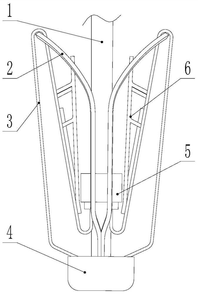
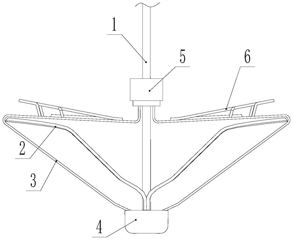
The invention relates to the field of medical instruments, in particular to a valve clamping device. The valve clamping device comprises a control rod, a first supporting piece, a clamping piece, at least one pair of folding pieces and at least one pair of closing pieces. The folding pieces are arranged on the two sides of the control rod respectively and correspond to the closing pieces. One end of the folding piece is rotationally connected with the control rod, the other end of the folding piece is movably connected with the first supporting piece, and the first supporting piece slides on the control rod; the closing piece is connected with the folding piece; and the clamping piece is arranged between the folding piece and the control rod. The opening and closing degree, namely the opening and closing degree of the valve, of the clamping device is adjusted by automatically adjusting the opening and closing angle through blood pressure driving; therefore, the effects of reducing blood regurgitation during cardiac contraction and reducing the resistance of blood passing through the valve during cardiac diastole are achieved.

Description

technical field [0001] The invention relates to the field of medical devices, in particular to a valve clamping device. Background technique [0002] Heart valves (aortic valve, pulmonary valve, mitral valve, tricuspid valve,) are an important part of the cardiovascular system. The heart valve plays a role similar to a one-way valve in the cardiovascular system. The blood passing through the heart valve can only pass along the flow direction of the valve, and cannot reverse the reverse flow, so that the blood in the vascular system can The blood flows in a fixed direction. [0003] Mitral regurgitation is a common valve disorder. Some of the existing techniques used to treat patients with mitral regurgitation include surgical replacement of the prosthetic valve or the natural mitral valve leaflets being stitched edge-to-edge (Alfierystitch), or the mitral valve Leaflet edge clipping, etc. [0004] At present, surgical intervention for mitral regurgitation mainly includes...

Claims


Application Information

Patent Timeline
IPC IPC(8): A61F2/24
CPCA61F2/2427A61F2/2442A61F2/2466
Inventor 阮成民肖建平林育坤曾杰姜小飞
Owner GUANGDONG PULSE MEDICAL SCI & TECH CO LTD
Learn More