
Numerically-controlled machine tool waste separating device and working method thereof

A technology of separation device and CNC machine tool, which is applied in the direction of magnetic separation, cleaning device, solid separation, etc., can solve the problems of troublesome waste treatment, inability to separate iron materials, and reduce waste treatment efficiency, so as to save electric energy, avoid repeated transportation, Reduce the effect of separation work

Pending Publication Date: 2021-08-10
QINGDAO HUANGHAI UNIV
View PDF0 Cites 4 Cited by
  • Summary
  • Abstract
  • Description
  • Claims
  • Application Information

AI Technical Summary

Problems solved by technology

[0004] The object of the present invention is to provide a kind of numerical control machine tool waste material separating device and its working method, aim at solving the common problem in the prior art that iron material and aluminum are mixed and then extruded into waste material blocks, although this method is fast, it cannot The iron in the waste is separated, which will cause certain troubles to the subsequent waste treatment and reduce the efficiency of waste treatment.

Method used


Image

  • Numerically-controlled machine tool waste separating device and working method thereof
  • Numerically-controlled machine tool waste separating device and working method thereof
  • Numerically-controlled machine tool waste separating device and working method thereof

Examples


Embodiment

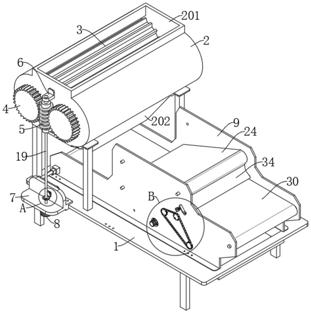
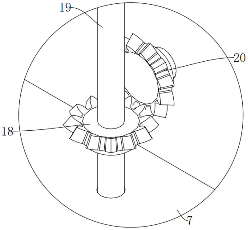
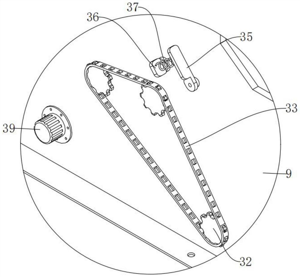
[0044] see Figure 1-10 , the technical solution provided by this embodiment is as follows:

[0045] A CNC machine tool waste separation device, comprising:

[0046] Workbench 1;

[0047] The crushing bin 2 is fixedly connected to the top of the workbench 1. The crushing bin 2 is provided with a feed port 201, a discharge port 202 and a crushing mechanism. The side of the workbench 1 is connected with a mounting frame 7 by bolts. The mounting frame 7 is provided with a driving mechanism, which is connected with the crushing mechanism to achieve crushing. The crushing mechanism includes two crushing teeth 3, two worm wheels 4 and a worm 5, and the two crushing teeth 3 are Rotationally connected between the side walls of the crushing bin 2, the two worm gears 4 are both rotatably connected to the side of the crushing bin 2, the axes of the two worm wheels 4 are fixedly connected to the crushing teeth 3 respectively, and the crushing bins Two mounting plates 6 are fixedly conn...


PUM


Abstract

The invention provides a numerically-controlled machine tool waste separating device and a working method thereof, and belongs to the field of waste treatment. The device comprises a workbench, a crushing bin fixedly connected to the top of the workbench, and a second conveying mechanism, wherein a feeding port, a discharging port and a crushing mechanism are arranged on the crushing bin, a mounting frame is connected to the side of the workbench through bolts, a driving mechanism is arranged on the mounting frame, and the driving mechanism is connected with the crushing mechanism to achieve crushing; the second conveying mechanism comprises a second conveying belt and three third rotating shafts, waste scraps are conveyed through a first conveying roller, and when the iron materials move to the side, close to a third conveying belt, of the second conveying belt, the adsorption effect of a magnetic adsorption plate is gradually lost, so that the iron materials fall to the upper side of the third conveying belt, other waste materials are conveyed to the upper side of a discharging groove through a first conveying belt, the separation and conveying effect is achieved, the iron materials and other materials in the waste materials are effectively separated, the subsequent separation work is reduced, and the working efficiency is improved.

Description

technical field [0001] The invention belongs to the field of waste material treatment, and in particular relates to a waste material separation device for a numerically controlled machine tool and a working method thereof. Background technique [0002] The CNC machine tool is a digitally controlled machine tool. After calculation and processing, various control signals are sent by the CNC device to control the movement of the machine tool, and the parts are automatically processed according to the shape and size required by the drawing. The CNC machine tool solves complex, precise, It is a flexible and high-efficiency automatic machine tool for small batch and multi-variety parts processing, which represents the development direction of modern machine tool control technology and is a typical mechatronics product. [0003] CNC machine tools will produce a lot of waste when processing parts. Most of these wastes are made of iron and aluminum. The existing technology usually mi...

Claims


Application Information

Patent Timeline
IPC IPC(8): B02C4/08B02C4/42B02C4/28B02C23/10B03C1/22B65G15/28B65G45/12
CPCB02C4/08B02C4/28B02C4/42B02C23/10B03C1/22B65G15/28B65G45/12
Inventor 王海艳宋爱利姜云春王娜李菊燕王培芹刘树涛
Owner QINGDAO HUANGHAI UNIV
Learn More