Mixing station waste slurry recycling process and device

A mixing station and slurry water technology, which is applied in cement mixing equipment, clay preparation equipment, dehydration/drying/thickened sludge treatment, etc., can solve the problem of unhelpful reduction of waste slurry in mixing stations, difficulty in accurately controlling the amount of mixing, and volume reduction To solve the problems such as limited waste pulp, to achieve the effect of significantly reducing the amount of waste pulp, reducing working hours and reducing work burden

Pending Publication Date: 2021-08-10
CHINA WEST CONSTR ACAD OF BUILDING MATERIALS CO LTD
View PDF12 Cites 2 Cited by
  • Summary
  • Abstract
  • Description
  • Claims
  • Application Information

AI Technical Summary

Problems solved by technology

However, its solid content is generally low and unstable. It is directly used in the production of concrete, and the reduction is limited, and the production mix ratio needs to be adjusted continuously, which brings a lot of inconvenience to the production management of the concrete mixing plant.
[0003] At present, the main disposal methods of waste slurry water in the mixing station are sedimentation filter press method and homogenization method. The mud cake produced by the filter press method is directly transported outside for disposal, and the disposal cost is high. In the process of homogenization method, there will be situations such as replenishing clean water, which is not good for the reduction and disposal of waste slurry water. Waste slurry is directly used in concrete production, and its dosage is difficult to control accurately, resulting in unstable concrete quality
[0004] Although the existing domestic waste slurry water treatment process and equipment of the mixing station can initially treat the waste slurry water of the mixing station, there are substantial defects, such as: the waste slurry treatment device cannot release a large amount of clean water, It is not beneficial to the reduction of waste slurry in the mixing station and other issues

Method used


Image

  • Mixing station waste slurry recycling process and device
  • Mixing station waste slurry recycling process and device
  • Mixing station waste slurry recycling process and device

Examples


Embodiment 1

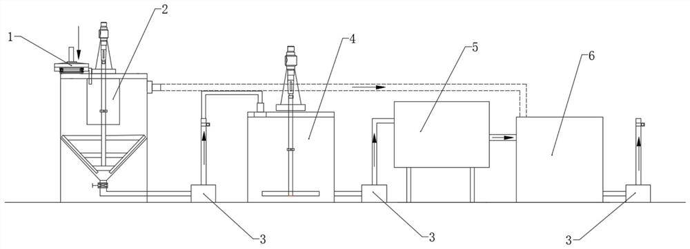
[0053] A process for reuse of waste slurry water in a mixing station, comprising the following steps:

[0054] S1. Separation

[0055] Use screening equipment to separate the particles with a particle size greater than 2mm in the waste slurry water produced by the mixing station to obtain the remaining waste slurry;

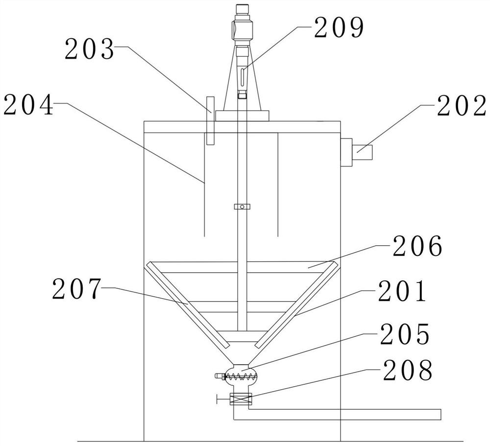
[0056] S2. Concentration

[0057] Add 0.01% of its volume to the waste slurry water obtained in step S1, and the concentration residence time in the concentrator is 60 minutes; respectively obtain clear water with a solid content of less than 0.1% and underflow waste slurry with a solid content of more than 20%;

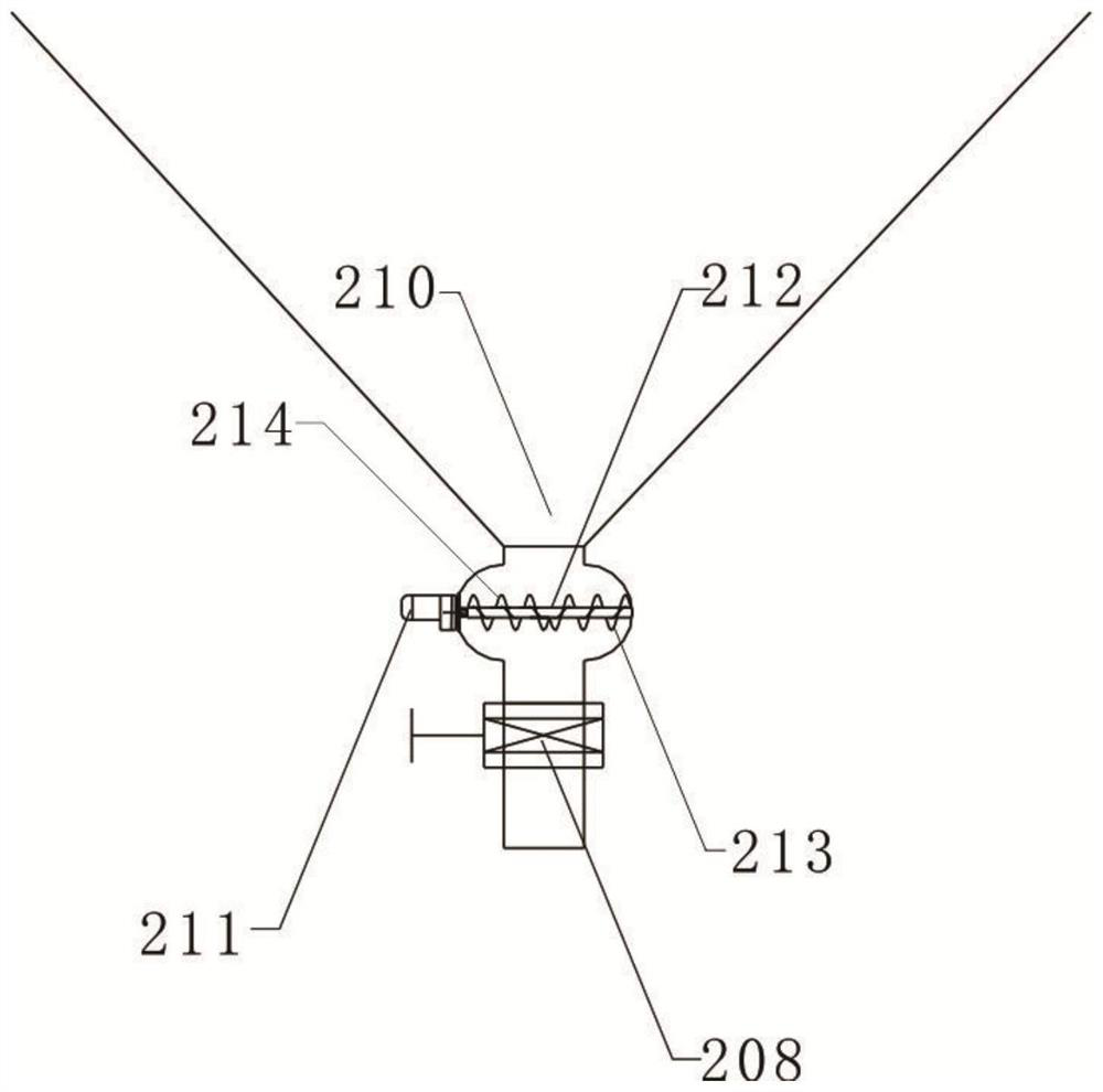
[0058] S3. Vacuum desliming

[0059] The underflow waste slurry obtained in step S2 is pumped into a deslimer, and deslimed in an environment of 0.04 MPa, and the waste residue and deslimed waste slurry are collected, and the deslimed waste slurry is returned to step S2 for further concentration.

Embodiment 2

[0061] A process for reuse of waste slurry water in a mixing station, comprising the following steps:

[0062] S1. Separation

[0063] Use screening equipment to separate the particles with a particle size greater than 2mm in the waste slurry water produced by the mixing station to obtain the remaining waste slurry;

[0064] S2. Concentration

[0065] Add 0.01% of its volume to the waste slurry water obtained in step S1, and the concentration residence time in the concentrator is 60 minutes; respectively obtain clear water with a solid content of less than 0.1% and underflow waste slurry with a solid content of more than 20%;

[0066] S3. Vacuum desliming

[0067] The underflow waste slurry obtained in step S2 is pumped into a deslimer, and deslimed in an environment of 0.05 MPa, and the waste residue and deslimed waste slurry are collected, and the deslimed waste slurry is returned to step S2 for further concentration.

Embodiment 3

[0069] A process for reuse of waste slurry water in a mixing station, comprising the following steps:

[0070] S1. Separation

[0071] Use screening equipment to separate the particles with a particle size greater than 2mm in the waste slurry water produced by the mixing station to obtain the remaining waste slurry;

[0072] S2. Concentration

[0073] Add 0.01% of its volume to the waste slurry water obtained in step S1, and the concentration residence time in the concentrator is 60 minutes; respectively obtain clear water with a solid content of less than 0.1% and underflow waste slurry with a solid content of more than 20%;

[0074] S3. Vacuum desliming

[0075] The underflow waste slurry obtained in step S2 is pumped into a deslimer, and deslimed in an environment of 0.06 MPa, and the waste residue and deslimed waste slurry are collected, and the deslimed waste slurry is returned to step S2 to continue to concentrate.


PUM


Abstract

The invention discloses a mixing station waste slurry recycling process and device. The process comprises the following steps of: S1, separation; S2, concentration; and S3, vacuum desliming. The device comprises a screening device, a concentrator, a waste slurry storage tank, a desliming machine and a clear water tank which are sequentially communicated. The mixing station waste slurry recycling process and device can treat and recycle mixing station waste slurry, the mixing station waste slurry enters the concentrator for rapid water-slurry separation after being treated by sand-stone separation equipment, overflow clear water can be directly used for concrete production and equipment and site cleaning, high-concentration waste slurry at the bottom enters efficient desliming equipment for water-solid separation, separated solid residues are loose and scattered and are directly recycled for production, and separated water is directly used for production or equipment and site cleaning. The mixing station waste slurry recycling process and device have the characteristic of efficiently treating mixing station solid waste at high value, and have the advantages of low treatment cost, zero solid waste emission, complete recycling, intelligent monitoring and control, environmental protection and the like.

Description

technical field [0001] The invention belongs to the technical field of concrete admixture production, and in particular relates to a process for reusing waste slurry water in a mixing station and a device thereof. Background technique [0002] Urban construction has a great demand for concrete and other building materials. During the production of concrete in the mixing station, a large amount of waste slurry water will be generated. The waste slurry water mainly comes from washing mixer trucks, pump trucks, conveyor belts, mixers and venues, etc. , so these waste slurry water contains aggregate, cement, fly ash, mineral powder, a small amount of mud, etc., which can be used as raw materials for concrete production. However, its solid content is generally low and unstable. It is directly used in the production of concrete, and the reduction is limited, and the production mix ratio needs to be adjusted continuously, which brings a lot of inconvenience to the production manage...

Claims


Application Information

Patent Timeline
Patent Type & Authority Applications(China)
IPC IPC(8): B28C5/08C02F11/12
CPCB28C5/0806C02F11/12
Inventor 王军高育欣杨文吴雄高达马建峰涂玉林
Owner CHINA WEST CONSTR ACAD OF BUILDING MATERIALS CO LTD
Why Eureka
Try Eureka