
Energy gathering ring and stove burner

A burner and energy-gathering technology, which is applied to household stoves, heating fuels, household appliances, etc., can solve the problems of high radiant heat loss in the energy-gathering circle and low thermal efficiency of the cooker, and achieves reduction of losses, good energy-gathering effect, and enhanced energy-gathering effect. absorption effect

Active Publication Date: 2021-08-10
NINGBO FOTILE KITCHEN WARE CO LTD
View PDF16 Cites 1 Cited by
  • Summary
  • Abstract
  • Description
  • Claims
  • Application Information

AI Technical Summary

Problems solved by technology

[0004] The technical problem to be solved by the present invention is to provide an energy-gathering ring and a stove burner in order to overcome the defect that the energy-gathering ring has a lot of radiation heat loss in the prior art, resulting in a relatively low improvement in the thermal efficiency of the cooker.

Method used


Image

  • Energy gathering ring and stove burner
  • Energy gathering ring and stove burner
  • Energy gathering ring and stove burner

Examples


Embodiment 1

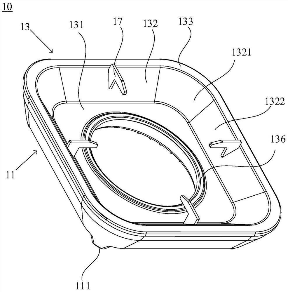
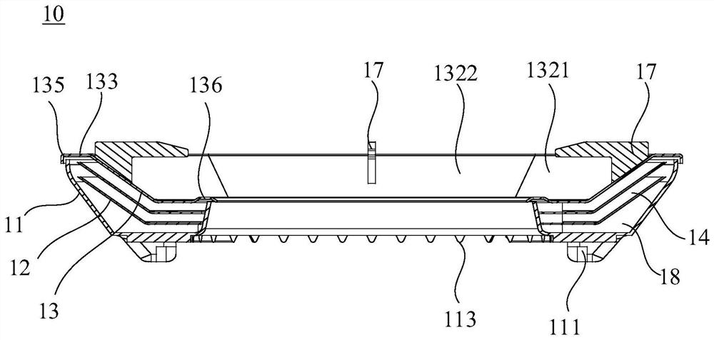
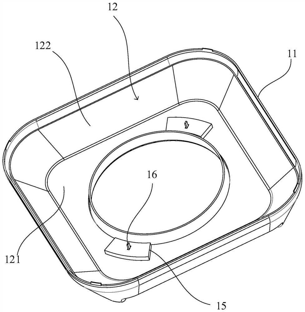
[0080] This embodiment provides an energy gathering ring 10 for a cooker burner. Such as Figure 1-4 As shown, the energy gathering ring 10 includes an annular lower layer body 11 , an annular upper layer body 13 and at least one middle layer body 12 . The lower layer body 11 has an annular cavity 18 with an opening facing upwards; the upper layer body 13 is coaxially arranged with the lower layer body 11, and is covered at the opening of the annular cavity 18; the middle layer body 12 is fixed in the annular cavity 18, and is placed between the lower layer body 11 and the A plurality of annular air heat insulation layers 14 distributed up and down are isolated between the upper layers 13 .

[0081] In this embodiment, the upper body 13 directly faces the combustion zone, which is used to reflect the heat radiation upwards and play the role of energy gathering. The middle layer body 12 is arranged in the annular cavity 18, so that between adjacent middle layer bodies 12, Bet...

Embodiment 2

[0100] This embodiment provides an energy gathering ring 10 for a cooker burner 100 . Such as Figure 5 As shown, the structure of the energy gathering ring 10 of this embodiment is basically the same as that of Embodiment 1, the difference is that: the outer ring of the upper side plate 132 of this embodiment has an annular horizontal portion 133, and the horizontal portion 133 corresponds to the side portion The position of 1322 has an upward protruding protruding block 134 , and the protruding block 134 is used to guide the smoke to the corner 1321 of the upper side plate 132 . By setting the protruding block 134 on the horizontal part 133, the area of ​​the smoke circulation channel corresponding to the side part 1322 of the horizontal part 133 is reduced, the exhaust resistance of this area is strengthened, the amount of smoke flowing through this area is reduced, and the smoke is forced The flow out from the four corners 1321 strengthens the heat absorption of the pot, ...

Embodiment 3

[0102]This embodiment also provides a cooker burner 100, including the energy gathering ring 10 described in any one of the above embodiments. The use of the energy gathering ring 10 in the cooker burner 100 can effectively reduce the heat conduction between the layers, reduce the loss of heat from the upper layer 13 to the lower layer 11, and strengthen the heat absorption of the pot. 10's energy-gathering effect is better.


PUM


Abstract

The invention discloses an energy gathering ring and a stove burner. The energy gathering ring comprises an annular lower layer body, an annular upper layer body, and at least one middle layer body, wherein the lower layer body is provided with an annular cavity with an upward opening; the upper layer body and the lower layer body are coaxially arranged, and an opening of the annular cavity is covered with the upper layer body; and the at least one middle layer body is fixed in the annular cavity, and a plurality of annular air heat insulation layers which are distributed up and down are isolated between the lower layer body and the upper layer body. The middle layer bodies are arranged in the annular cavity, so that the air heat insulation layers can be formed between every two adjacent middle layer bodies, between the adjacent upper layer body and the middle layer body and between the adjacent middle layer body and the lower layer body, the air heat insulation layers can effectively reduce heat conduction between the layer bodies, the loss of heat from the upper layer body to the lower layer body is reduced, heat absorption of a cookware is enhanced, and the energy gathering effect of the energy gathering ring is better.

Description

technical field [0001] The invention relates to an energy gathering ring and a cooker burner. Background technique [0002] At present, the highest performance cooker has a thermal load of 4.5kW and a thermal efficiency of 75%. As the market competition for kitchen appliances becomes more and more fierce, all enterprises are concentrating on the development of cookers with greater firepower, higher thermal efficiency and easy cleaning. . There are no more than two ways to improve the thermal efficiency under the premise of heavy load. One is to improve the combustion state of the burner flame and strengthen the absorption of combustion heat; the other is to reduce the energy loss of combustion heat. In order to reduce the energy loss of combustion heat and improve the thermal efficiency of the cooker, an energy gathering ring is usually arranged around the outer ring fire cover of the cooker. Reflected back to the bottom of the pot, thereby reducing the energy loss of comb...

Claims


Application Information

Patent Timeline
IPC IPC(8): F24C15/34F24C15/10F24C15/14F24C15/22F24C3/08
CPCF24C15/34F24C15/22F24C15/14F24C15/107F24C3/085
Inventor 朱志新刘帅
Owner NINGBO FOTILE KITCHEN WARE CO LTD
Learn More