Self-gating device based on two-dimensional molybdenum oxide/molybdenum sulfide laminated structure and manufacturing method thereof
A stacked structure and manufacturing method technology, applied in the field of microelectronics, can solve the problems of unguaranteed deposition uniformity and complicated process, and achieve the effects of reducing power consumption, strong miniaturization, and reducing leakage current
- Summary
- Abstract
- Description
- Claims
- Application Information
AI Technical Summary
Problems solved by technology
Method used
Image
Examples
Embodiment approach
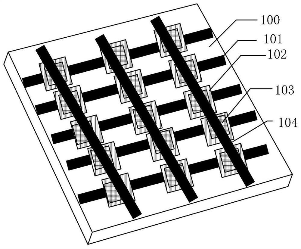
[0022] The invention discloses an embodiment of a method for manufacturing a self-gated device based on a two-dimensional material stack structure, which includes the following steps:
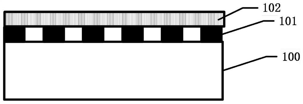
[0023] In the first step, the pattern of the lower electrode is exposed on the substrate 100, the lower electrode 101 is prepared by physical vapor deposition, and the patterned lower electrode 101 is obtained by lift-off. Such as figure 2 shown;
[0024] In the second step, based on the surface of the lower electrode 101, the dielectric layer I102 is grown in situ by magnetron sputtering combined with post-annealing process, such as image 3 shown;
[0025] In the third step, based on the surface transfer of the dielectric layer I102, nanosheets are prepared by chemical vapor deposition as the dielectric layer II103, such as Figure 4 shown;
[0026] The fourth step is to pattern the upper electrode based on the surface alignment exposure of the dielectric layer II 103, deposit the upper ...
Embodiment 2
[0033] The invention discloses an embodiment of a method for manufacturing a self-gated device based on a two-dimensional material stack structure, which includes the following steps:
[0034] In the first step, based on the surface of the substrate 100, gold is deposited as the lower electrode 101 by physical vapor deposition method, with a thickness of 100 nm, the mask pattern of the lower electrode is exposed, and the patterned lower electrode 101 is obtained through a dry etching process;
[0035] In the second step, based on the surface of the lower electrode 101, a dielectric layer I 102 is grown in-situ with a thickness of 3 nm by using a combination of atomic layer deposition and post-annealing processes;
[0036] The third step is to peel off the bulk material based on the surface of the dielectric layer I102 as the dielectric layer II103 with a thickness of 20nm;
[0037] The fourth step is to pattern the upper electrode based on the surface alignment exposure of the...
Embodiment 3
[0039] The invention discloses an embodiment of a method for manufacturing a self-gated device based on a two-dimensional material stack structure, which includes the following steps in sequence:
[0040] In the first step, based on the method of physical vapor deposition above the substrate 100, chromium is prepared as the lower electrode 101 with a thickness of 80nm, and the patterned lower electrode 101 is obtained through an etching process;
[0041] In the second step, the dielectric layer I102 is grown by chemical vapor deposition and transferred to the surface of the lower electrode 101, with a thickness of 10 nm;
[0042] In the third step, the dielectric layer II 103 is grown by chemical vapor deposition method and transferred to the surface of the lower dielectric layer I 102 in precise alignment, with a thickness of 6 nm;
[0043] The fourth step is to pattern the upper electrode based on the surface alignment exposure of the dielectric layer II 103, and deposit tungs...
PUM
| Property | Measurement | Unit |
|---|---|---|
| thickness | aaaaa | aaaaa |
| thickness | aaaaa | aaaaa |
| thickness | aaaaa | aaaaa |
Abstract
Description
Claims
Application Information
 - R&D
- Intellectual Property
- Life Sciences
- Materials
- Tech Scout
- Unparalleled Data Quality
- Higher Quality Content
- 60% Fewer Hallucinations
Browse by: Latest US Patents, China's latest patents, Technical Efficacy Thesaurus, Application Domain, Technology Topic, Popular Technical Reports.
© 2025 PatSnap. All rights reserved.Legal|Privacy policy|Modern Slavery Act Transparency Statement|Sitemap|About US| Contact US: help@patsnap.com


