
A Positionless Control Method for Switched Reluctance Motor Based on Linear Inductance Conversion Method
A technology of switched reluctance motor and control method, which is applied in the direction of motor control, AC motor control, control system, etc., to achieve the effect of simple and easy method, less measurement work, and high estimation accuracy
- Summary
- Abstract
- Description
- Claims
- Application Information
AI Technical Summary
Problems solved by technology
Method used
Image

Examples
Embodiment Construction
[0029] The embodiments of the present invention are described in detail below, and the embodiments are exemplary and intended to explain the present invention, but should not be construed as a limitation of the present invention.
[0030] The motor used in this embodiment is a 1kW three-phase 12 / 8-pole switched reluctance motor.
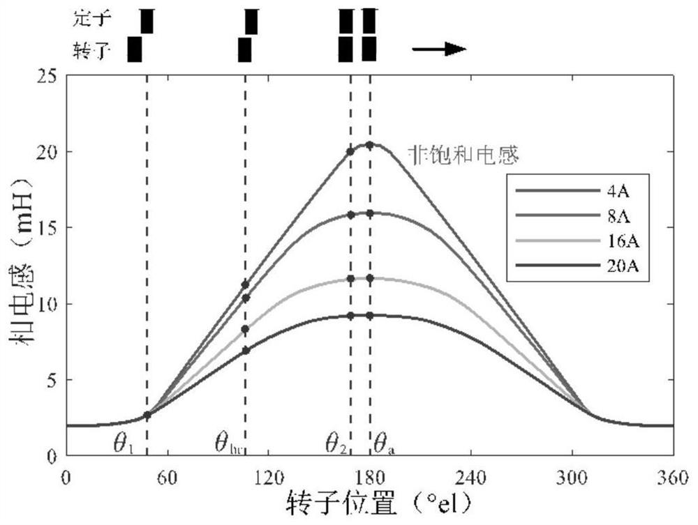
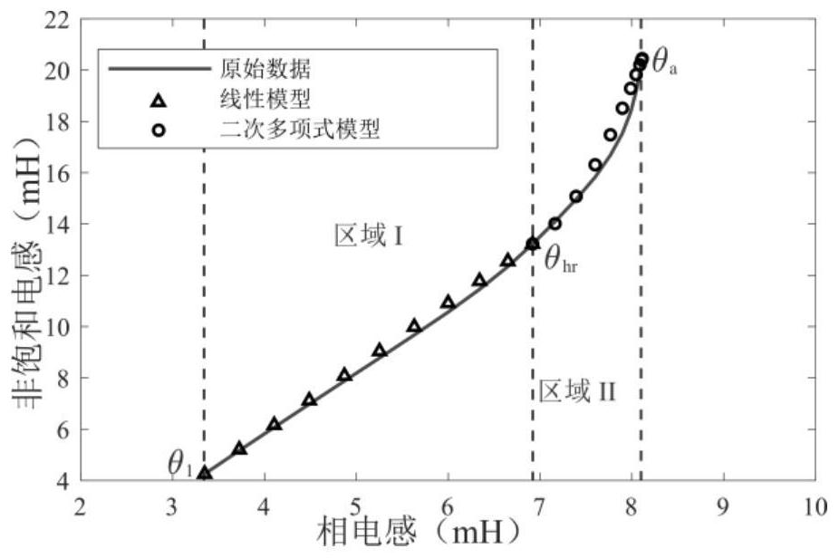
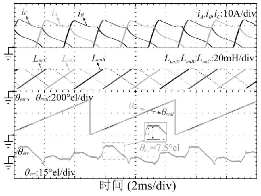
[0031] Step 1: Obtain the characteristics of the inductance versus current of the switched reluctance motor at four special positions by the torque balance method, including the non-saturated inductance L un (θ 1 ), L un (θ 2 ), L un (θ hr ), L un (θ a ), and the phase voltage and phase current of the switched reluctance motor are obtained by measuring the current sensor and voltage sensor; where θ 1 Represents the rotor position when the front edge of the stator of the switched reluctance motor coincides with the rear edge of the rotor, θ 2 Represents the rotor position when the front edge of the stator and the front edge of the rotor coinci...
PUM
 Abstract
Description
Claims
Application Information