Resistance characteristic electrical variable measuring device of electronic component

A technology of electronic components and measuring devices, which is applied in the direction of measuring devices, measuring device casings, and measuring electrical variables, etc., can solve the problems of reducing measurement efficiency, affecting the accuracy of electronic component measurement, and not being able to clean dust, so as to avoid measurement efficiency, Avoid the effect of more dust adhesion

Active Publication Date: 2021-08-13
江苏振宁半导体研究院有限公司
View PDF5 Cites 4 Cited by
  • Summary
  • Abstract
  • Description
  • Claims
  • Application Information

AI Technical Summary

Problems solved by technology

[0004] The purpose of the present invention is to solve the problem that in the prior art, the dust attached to the conductive column cannot be cleaned, which will affect the accuracy of the measurement of the electronic components during the measurement, and the electronic components need to be manually removed after the measurement, which reduces the Measurement efficiency and other issues, while the electrical variable measurement device for the resistance characteristics of electronic components

Method used


Image

  • Resistance characteristic electrical variable measuring device of electronic component
  • Resistance characteristic electrical variable measuring device of electronic component
  • Resistance characteristic electrical variable measuring device of electronic component

Examples


Embodiment 1

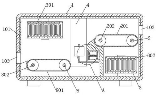
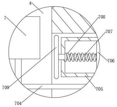
[0029] Embodiment 1: refer to Figure 1-8 , the electrical variable measuring device for the resistance characteristics of electronic components, including a box body 1, an electronic component body 5, and also includes: a material inlet 102 and a material outlet 103, which are respectively provided on both sides of the box body 1; a frame 4 is fixedly connected to the box body The inner wall of the body 1; the self-locking assembly is arranged on the frame 4; the conductive ring 405 is arranged on the self-locking assembly and is plugged and connected with the electronic component body 5; and cooperates with the conductive ring 405 to transmit electrical signals to the electronic component body 5 A signal source, and an oscilloscope cooperating with the conductive ring 405; a cleaning assembly, arranged on one side of the conductive ring 405, for cleaning the dust attached to the electronic component body 5; a reciprocating assembly, arranged on one side of the frame 4, and th...

Embodiment 2

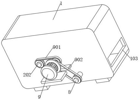
[0035] Embodiment 2: refer to figure 2 , Figure 4 with Figure 7 , the resistance characteristic electrical variable measuring device of the electronic component is basically the same as Embodiment 1, and furthermore, the self-locking assembly includes a motor 9, a reciprocating screw mandrel 402, a support plate 404, and the frame 4 is fixedly connected with a placement plate 401, and the electronic The component body 5 is located on the placement plate 401, the motor 9 is fixedly connected to the side wall of the box body 1, the reciprocating screw rod 402 is rotatably connected to the frame 4, the support plate 404 is screwed to the reciprocating screw rod 402, and the output end of the motor 9 is connected to the reciprocating screw rod 402 is fixedly connected, and the support plate 404 is attached to the electronic component body 5 .

[0036] A guide rod 403 is fixedly connected to the frame 4 , and the guide rod 403 is slidably connected to a support plate 404 .

...

Embodiment 3

[0038] Embodiment 3: refer to Figure 4 , Figure 5 with Figure 8 , the resistance characteristic electrical variable measuring device of the electronic component is basically the same as Embodiment 1, and furthermore, the cleaning assembly includes a sleeve 6, a support rod 607, and a collar 604, and the sleeve 6 and the collar 604 are all fixedly connected On the supporting plate 404, the supporting rod 607 is fixedly connected to the frame 4, the lower pressing plate 601 is slidably connected in the sleeve one 6, the lower pressing plate 601 is fixedly connected with the inner wall of the sleeve one 6 with a spring one 602, the lower pressing plate 601 and the supporting plate 404 Slidingly connected, the inner wall of the collar 604 is fixedly connected with the nozzle 605 and the brush 606 respectively, and the sleeve one 6 and the nozzle 605 are connected through the conduit one 603 .

[0039] When the self-locking assembly clamps the electronic component body 5, the ...


PUM


Abstract

The invention discloses a resistance characteristic electrical variable measuring device of an electronic component, and belongs to the technical field of measuring equipment. The resistance characteristic electrical variable measuring device of the electronic component comprises a box body and an electronic component body, and further comprises a feeding hole and a discharging hole which are respectively formed in two sides of the box body; a frame, which is fixedly connected to the inner wall of the box body; a self-locking assembly which is arranged on the frame; a conducting ring which is arranged on the self-locking assembly and is connected with the electronic component body in an inserting manner; and a signal source which is matched with the conducting ring to transmit an electric signal to the electronic component body. According to the invention, when an electronic component body is measured, a limiting effect can be achieved, the situation that displacement occurs during measurement and measurement of the electronic component body is affected is avoided, dust attached to the conductive column can be cleaned while limiting is conducted, and the situation that the measurement accuracy is affected due to the fact that a large amount of dust is attached is avoided; after measurement, automatic blanking is performed and workers do not need to manually take the electronic component bodies, so that the measurement efficiency is prevented from being affected.

Description

technical field [0001] The invention relates to the technical field of measuring equipment, in particular to a device for measuring electrical variables of resistance characteristics of electronic components. Background technique [0002] Electronic components are the basic elements in electronic circuits, usually individually packaged, and have two or more leads or metal contacts. Electronic components must be connected to each other to form an electronic circuit with specific functions, such as amplifiers, radio receivers, Oscillators, etc. Resistance is one of the core parameters of electronic components. Resistance is mainly affected by factors such as material and temperature. In order to measure the resistance characteristics of electronic components, it can be judged whether the electronic components meet the quality requirements. [0003] At present, electric variable measuring devices are used when measuring the resistance characteristics of electronic components, b...

Claims


Application Information

Patent Timeline
Patent Type & Authority Applications(China)
IPC IPC(8): G01R27/02G01R1/02G01R1/04B08B1/00B08B5/02B08B7/04
CPCB08B1/002B08B5/02B08B7/04G01R1/02G01R1/0408G01R27/02
Inventor 彭丽媛
Owner 江苏振宁半导体研究院有限公司
Why Eureka
Try Eureka