
Multi-channel high-voltage circuit for optical module

A high-voltage circuit and optical module technology, applied in the field of optical communication, to achieve the effect of reducing the layout area

Inactive Publication Date: 2021-08-13
武汉英飞光创科技有限公司
View PDF5 Cites 1 Cited by
  • Summary
  • Abstract
  • Description
  • Claims
  • Application Information

AI Technical Summary

Problems solved by technology

However, there is currently no single chip with 4 high-voltage outputs on the market, and only chip manufacturers are doing preliminary market research

Method used


Image

  • Multi-channel high-voltage circuit for optical module

Examples


Embodiment Construction

[0025] The following will clearly and completely describe the technical solutions in the embodiments of the present invention with reference to the accompanying drawings in the embodiments of the present invention. Obviously, the described embodiments are only some, not all, embodiments of the present invention. Based on the embodiments of the present invention, all other embodiments obtained by persons of ordinary skill in the art without making creative efforts belong to the protection scope of the present invention.

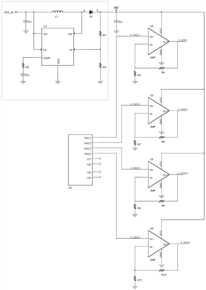
[0026] Such as figure 1 , an embodiment of the present invention provides a multi-channel high-voltage circuit for an optical module, including a boost circuit, a controller U4 and an operational amplifier circuit, the controller U4 is an MCU or a DAC chip, and one end of the boost circuit is connected to a The external power supply voltage VCC_IN, the external power supply voltage VCC_IN is 3.3V, the other end of the boost circuit is the voltage output port H...


PUM


Abstract

The invention provides a multi-channel high-voltage circuit for an optical module, which comprises a booster circuit, a controller U4 and an operational amplifier circuit. One end of the booster circuit is connected with an external power supply voltage VCCIN, the other end of the booster circuit is a voltage output port HV, and the operational amplifier circuit comprises a plurality of high-voltage generating circuits. A power supply port of each high-voltage generation circuit is electrically connected with a voltage output port HV, a positive input port of each high-voltage generation circuit is electrically connected with a digital-to-analog conversion port of the controller U4, and the positive input ports of the high-voltage generation circuits are in one-to-one correspondence with the digital-to-analog conversion port of the controller U4. According to the invention, reverse bias of multiple APDs is realized by using a mode of one boost circuit and an operational amplifier, and compared with a traditional four-way boost circuit, the layout area of a PCB is reduced.

Description

technical field [0001] The invention relates to the technical field of optical communication, in particular to a multi-channel high-voltage circuit for an optical module. Background technique [0002] With the popularity of 100G optical modules, long-distance application scenarios are also increasing. Generally, for short-distance (such as 10km) optical modules, the optical device type at the receiving end is PIN, but when the distance becomes longer, the receiving optical device must use APD. Because the APD has a larger gain multiple, it can realize the identification and detection of weak signals. [0003] As we all know, APD has a higher gain when it works at a reverse bias voltage (generally 20-70V). For 4*25G 100G optical modules, 4 APDs are needed, so 4 high-voltage circuits are required. However, there is currently no single chip with 4 high-voltage outputs on the market, and only chip manufacturers are doing preliminary market research. [0004] Therefore, it is...

Claims


Application Information

Patent Timeline
Patent Type & Authority Applications(China)
IPC IPC(8): H04B10/40
CPCH04B10/40
Inventor 朱德锋谢顶波
Owner 武汉英飞光创科技有限公司
Learn More