Prefabricated T-beam prefabricated universal beam manufacturing pedestal and construction method

A technology for making beam pedestals and universal systems, which is applied in the direction of manufacturing tools, unloading devices, mold fixing devices, etc., can solve the problems of prefabricated pedestals not being used concurrently, achieve high construction efficiency, strong mobility, and improve site utilization.

Inactive Publication Date: 2021-08-17
CCCC SECOND HARBOR ENG
View PDF7 Cites 1 Cited by
  • Summary
  • Abstract
  • Description
  • Claims
  • Application Information

AI Technical Summary

Problems solved by technology

[0009] The main purpose of the present invention is to provide an assembled T-beam prefabricated universal girder pedestal and its construction method to solve the problem that the prefabricated pedestal cannot be used concurrently due to the bottom width

Method used


Image

  • Prefabricated T-beam prefabricated universal beam manufacturing pedestal and construction method
  • Prefabricated T-beam prefabricated universal beam manufacturing pedestal and construction method
  • Prefabricated T-beam prefabricated universal beam manufacturing pedestal and construction method

Examples


Embodiment 1

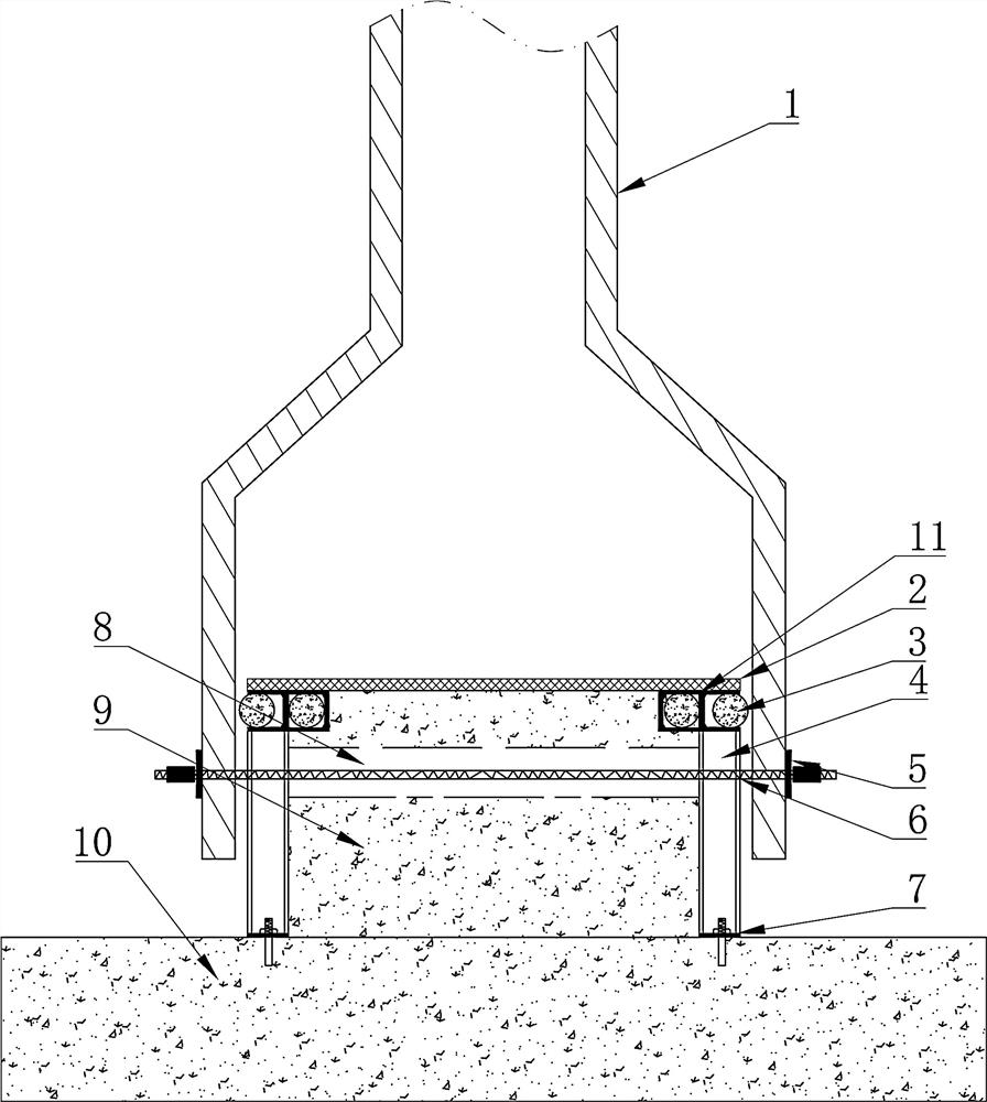
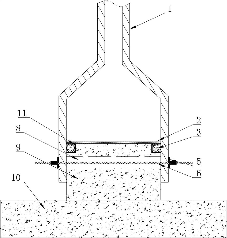
[0037] Such as Figure 1-6 As shown, an assembled T-beam prefabricated universal beam-making pedestal, beam formwork 1 is provided on both sides of the beam-making pedestal 9, the beam formwork 1 is slidingly connected with the beam-making pedestal 9, and the beam formwork 1 is connected to the beam-making pedestal 9 through a locking structure. connection, the beam-making platform 9 is also provided with at least one slurry-stopping groove 11, the inside of the slurry-stopping groove 11 is provided with a slurry-stopping bar 3, and the inner wall of the beam template 1 is against the slurry-stopping bar 3. Both sides of the beam-making pedestal 9 are provided with channel steel columns 4, at least one slurry-stopping groove 11 is arranged on the channel steel column 4, the inner wall of the beam template 1 is against the channel steel column 4, and the lower end of the channel steel column 4 is set by an expansion bolt 7. on the foundation pad 10. The locking structure inclu...

Embodiment 2

[0048] Further illustrate in conjunction with embodiment 1, Figure 1-6 As shown, on both sides of the beam-making base 9, first install the slurry-stop groove 11, install the slurry-stop rod 3 inside the slurry-stop groove 11, and then install the beam formwork 1, and the pull screw 6 passes through the beam formwork 1 and the through groove 8 on both sides to lock Tightly on the beam making pedestal 9, place the steel panel 2 at the bottom of the beam at the beam making pedestal 9.

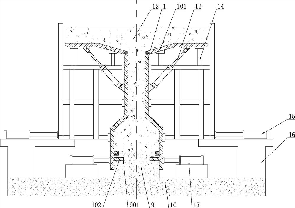
[0049] Adjust the width of the beam formwork 1, place the channel steel column 4 on both sides of the beam making platform 9, the bottom is locked on the foundation cushion 10 by the expansion bolt 7, and then install the second grouting tank 11 on the channel steel column 4 to stop the grouting The slurry rod 3 is installed inside the groove 11, and then the beam formwork 1 and the through groove 8 on both sides are passed through the beam formwork 1 and the through groove 8 on both sides by th...


PUM


Abstract

The invention provides a prefabricated T-beam prefabricated universal beam manufacturing pedestal and a construction method. Beam formworks are arranged on two sides of a beam manufacturing pedestal, the beam formworks are in sliding connection with the beam manufacturing pedestal, the beam formworks are connected with the beam manufacturing pedestal through locking structures, the beam manufacturing pedestal is further provided with at least one grout stopping groove, grout stopping rods are arranged in the grout stopping grooves, and the inner walls of the beam formworks abut against the grout stopping rods. The construction cost is greatly reduced. The universal pedestal can greatly improve the site utilization rate of a prefabrication site and greatly reduce land acquisition and construction costs of the T-beam prefabrication site. The universal T-beam prefabricating pedestal is high in maneuverability.

Description

technical field [0001] The invention relates to the field of T-beam prefabrication, in particular to an assembled T-beam prefabricated general-purpose beam base and a construction method. Background technique [0002] Expressway bridges are designed to meet different terrain and crossing requirements. Bridge spans are often set to 30m and 40m, and the corresponding 30m and 40m prefabricated T-beams are widely used in expressway construction. [0003] However, in view of the demand for stressed structures, the design of the bottom width of 30m and 40m beams in my country is inconsistent. The bottom width of 30m beams is generally 50cm, and the bottom width of 40m beams is 60cm. 30m and 40m beams are often solved by the following two ways to solve the problem of prefabricated pedestals not being used concurrently due to the bottom width: [0004] 1. Build 30m and 40m prefabricated pedestals respectively under the premise that the prefabricated site is not restricted. [0005...

Claims


Application Information

Patent Timeline
Patent Type & Authority Applications(China)
IPC IPC(8): B28B7/02B28B13/06B28B17/00
CPCB28B7/02B28B7/0002B28B7/0017B28B13/06B28B17/00
Inventor 于得安周范武吕双江张国庆张芙蓉王钊罗毅夏军林
Owner CCCC SECOND HARBOR ENG
Why Eureka
Try Eureka