
Functional ceramic preparation equipment

A technology for functional ceramics and equipment, which is applied in the field of functional ceramics preparation equipment, can solve the problems of reducing diameter and width, and unsmooth exhaust of flue gas, and achieves good effect.

Active Publication Date: 2021-08-17
怀仁县恒益陶瓷有限公司
View PDF6 Cites 1 Cited by
  • Summary
  • Abstract
  • Description
  • Claims
  • Application Information

AI Technical Summary

Problems solved by technology

[0004] When the ceramic raw materials are dried in the sintering furnace, a large amount of heat will be generated during the sintering process due to the addition of plasticizers to the raw materials. During the exhaust gas operation, part of the particle crystal molecules of the materials will be discharged with the heat and pass through the smoke. When it is in the cavity, it is easy to stay on the wall and then adhere and condense, so that the inner wall of the smoke cavity is reduced in diameter due to the attachment, resulting in unsmooth exhaust gas flow.

Method used


Image

  • Functional ceramic preparation equipment
  • Functional ceramic preparation equipment
  • Functional ceramic preparation equipment

Examples


Embodiment 1

[0031] as attached figure 1 To attach Image 6 Shown:

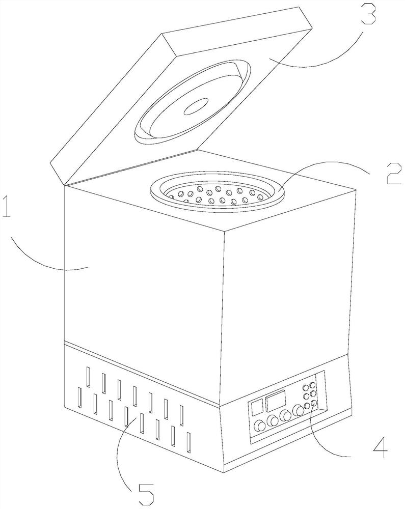
[0032] The present invention provides a kind of functional ceramic preparation equipment, its structure is provided with box body 1, sintering chamber 2, top cover 3, control panel 4, operation box 5, and described sintering chamber 2 and box body 1 are integrated structure and are arranged in At the middle end position, the top cover 3 is hingedly connected to the top of the box body 1, the top cover 3 is movably engaged above the sintering chamber 2, the operation box 5 is located at the bottom end of the box body 1, and the control The panel 4 is arranged at the lower end of the outer side of the box body 1 .

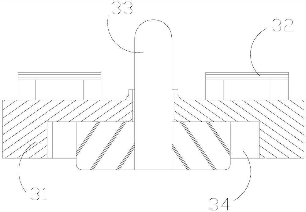
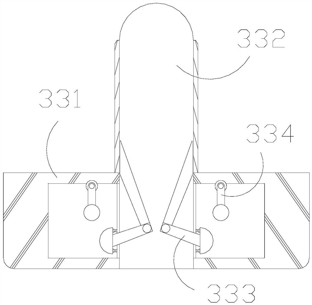
[0033] The top cover 3 is provided with a solid plate 31, a handle 32, a smoke exhaust device 33, and a draw-in groove 34. The draw-in groove 34 and the solid plate 31 are integrated structures and are embedded in the inner side thereof. The handle 32 is embedded Fixedly installed on the top of the solid boar...

Embodiment 2

[0040] as attached Figure 7 To attach Figure 9 Shown:

[0041] Wherein, the moving aid body 334 is provided with a folding rod b1, a variable ball b2, and a plug b3. The plug b3 is interpenetrated and movably matched. The folding rod b1 is a stretchable plate. The changing ball b2 is a circular structure with magnetic force and can be deformed in size. The changing ball b2 is Next, the displacement transformation is carried out with the assistance of the folding rod b1.

[0042] Wherein, the variable ball b2 is provided with an outer ring b21, a fixed ring b22, and a telescopic frame b23, the fixed ring b22 is located inside the outer ring b21, and the telescopic frame b23 is connected between the outer ring b21 and the fixed ring b22 and moves Cooperate, the outer ring b21 has a ring structure, the fixed ring b22 is a ring with a fixed diameter, and the telescopic frame b23 is flexible, and the outer ring b21 is ring-shaped under the telescopic cooperation of the telesco...


PUM


Abstract

The invention discloses functional ceramic preparation equipment. The functional ceramic preparation equipment is structurally provided with a box body, a sintering chamber, a top cover, a control panel and an operation box; upward thrust is generated on a connecting frame through air flow, the connecting frame is made to swing and fold, an arc block is driven to assist an elastic block to generate power, reverse elastic jacking is generated immediately under the elastic property of the arc block, the elastic block can continuously bounce and circularly eject the arc block under the elastic assistance of the elastic block and the telescopic elastic cooperation of a sleeve frame, and therefore, the sliding block can integrally do displacement movement to a greater extent to drive a movable body to move in a longer area, and a shovel plate can shovel and scrape the inner wall of a cigarette cavity better. A collision block sinks into the inner side of the shovel plate under the telescopic connection of a connecting rod through the magnetism of the arc block and the repulsive magnetic force of the movement assisting body, collision force is generated on the shovel plate to enable substances shoveled and scraped from the end face of the shovel plate to be shaken off conveniently, and therefore, the situation that hot gas drives part of particle molecules to be drained and attached to the wall face of a smoke cavity is avoided.

Description

technical field [0001] The invention belongs to the technical field of functional ceramic preparation, and more specifically relates to a functional ceramic preparation equipment. Background technique [0002] Ceramic products are widely used in people's production and life. Ceramics are also divided into ordinary ceramics and special ceramics. Functional ceramics are one of the special ceramics. They are ceramic products with electromagnetic properties and chemical properties. The drying and sintering of ceramics is One of the important processes in the preparation of ceramics is usually dried and shaped in a sintering furnace. [0003] Based on the inventor's discovery above, the existing functional ceramic preparation equipment has the following deficiencies: [0004] When the ceramic raw materials are dried in a sintering furnace, a large amount of heat will be generated during the sintering process due to the addition of plasticizers to the raw materials. During the ex...

Claims


Application Information

Patent Timeline
Patent Type & Authority Applications(China)
IPC IPC(8): F27B17/00
CPCF27B17/005F27M2003/04
Inventor 蔡建国
Owner 怀仁县恒益陶瓷有限公司
Learn More