Electroplating machine and electroplating method thereof

A technology of electroplating machine and electroplating parts, applied in the direction of electrolysis process, electrolysis components, cells, etc., can solve the problems of affecting product quality, long time, easy to produce errors, etc., and achieve the effect of improving electroplating effect, improving smoothness and improving quality

Pending Publication Date: 2021-08-20
王兆诚
View PDF1 Cites 0 Cited by
  • Summary
  • Abstract
  • Description
  • Claims
  • Application Information

AI Technical Summary

Problems solved by technology
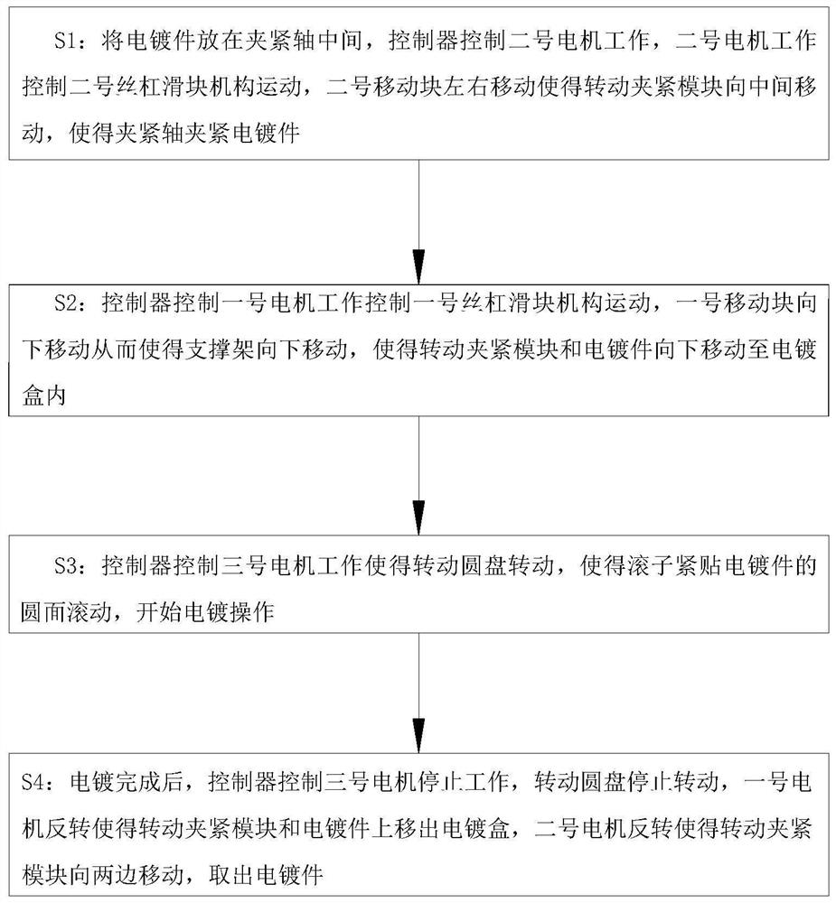
[0005] In order to make up for the deficiencies of the prior art, when the electroplating parts are clamped in the prior art, the clamped part cannot be electroplated. It is usually necessary to disassemble the electroplating parts after the electroplating is completed and re-clamp for secondary electrop

Method used


Image

  • Electroplating machine and electroplating method thereof
  • Electroplating machine and electroplating method thereof
  • Electroplating machine and electroplating method thereof

Examples


Example Embodiment

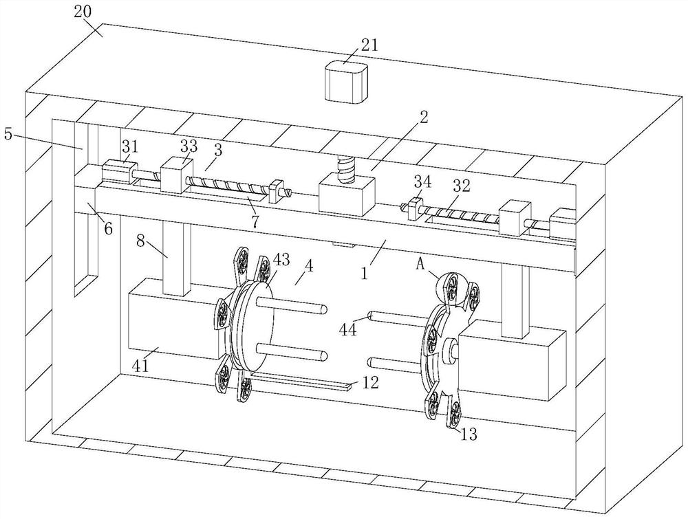
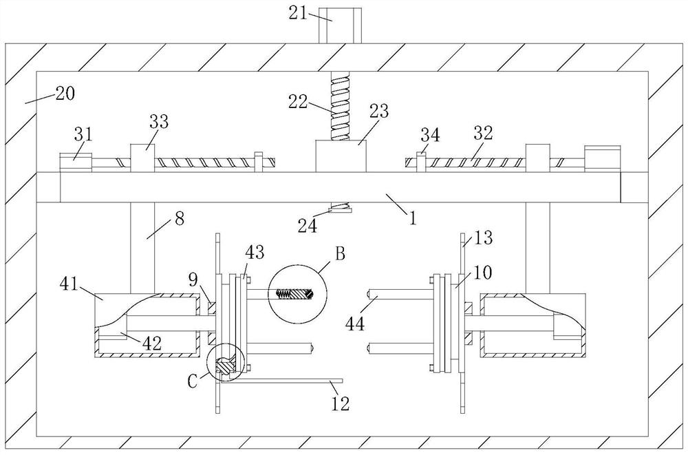
[0038] As an embodiment of the present invention, a cavity 441 is provided in the clamping shaft 44; the cavity 441 is slidably connected to a slider 442; the roller 45 is rotated to be connected to the slider 442; The slider 442 is retracted from one end of the roller with a spring 443; the spring 443 is inherently connected to one end of the slider 442 on the inner wall of the cavity 441; when operating, by providing a spring 443, the clamping axis 44 is held at the clamping axis 44 When the plating parts, the roller 45 is buffered with the slider 442 extrusion spring 443, preventing wear in the clamping process, thereby increasing the surface of the electroplating surface, which further facilitates the progression of electroplating, and improving the effect of electroplating, Improve the quality of the product.

[0039] As an embodiment of the present invention, the side surface of the rotating disc 43 is provided with a disc groove 10, and the bottom slide in the disc recess 1...


PUM


Abstract

The invention belongs to the technical field of electroplating, and particularly relates to an electroplating machine and an electroplating method. The electroplating machine comprises a supporting frame, a first lead screw sliding block mechanism, second lead screw sliding block mechanisms, a controller, a rotary clamping module and an electroplating box, wherein the first lead screw sliding block mechanism comprises a first motor, a first lead screw, a first moving block and a stop block, the stop block is fixedly connected to the lower end of the first lead screw, the first moving block is fixedly connected to the upper end face of the middle of the supporting frame, sliding grooves are formed in the left side wall and the right side wall of the inner side of the electroplating box correspondingly, the left end and the right end of the supporting frame are fixedly connected with limiting sliding blocks, the limiting sliding blocks are in sliding connection with the sliding grooves, and the two second lead screw sliding block mechanisms are arranged. According to the electroplating machine, the controller is used for controlling a third motor to work, so that a rotating disc can rotate, rollers can roll close to the circular face of an electroplated piece, the position of the clamping contact part of the electroplated piece can be changed all the time, the clamping part can also be electroplated, secondary electroplating is not needed during electroplating, and time and labor are saved.

Description

technical field [0001] The invention belongs to the technical field of electroplating, in particular to an electroplating machine and an electroplating method thereof. Background technique [0002] Electroplating is the process of plating a thin layer of other metals or alloys on the surface of certain metals using the principle of electrolysis. It is a process of using electrolysis to attach a layer of metal film to the surface of metal or other material parts to prevent metal oxidation ( Such as rust), improve wear resistance, conductivity, reflectivity, corrosion resistance (copper sulfate, etc.) The cations are reduced to form a coating on the surface of the workpiece to be plated. In order to eliminate the interference of other cations and make the coating uniform and firm, it is necessary to use a solution containing metal cations as the electroplating solution to keep the concentration of metal cations in the coating unchanged. The purpose of electroplating is to pl...

Claims


Application Information

Patent Timeline
IPC IPC(8): C25D17/00C25D17/06C25D21/10
CPCC25D17/00C25D17/06C25D21/10
Inventor 王兆诚王贺
Owner 王兆诚
Why Eureka
Try Eureka