
High-vacuum metal powder valve

A metal powder and high-vacuum technology, which is applied in the direction of valve lift, valve details, valve device, etc., can solve the problems that the valve body cannot effectively control the amount of powder, and the valve body seal cannot meet the process requirements, so as to reduce erosion and improve Effects of service life, safety and service life improvement

Inactive Publication Date: 2021-08-20
SINO EURO MATERIALS TECH OF XIAN CO LTD
View PDF5 Cites 0 Cited by
  • Summary
  • Abstract
  • Description
  • Claims
  • Application Information

AI Technical Summary

Problems solved by technology

[0004] The invention proposes a high-vacuum metal powder valve, which solves the problems in the prior art that the sealing of the valve body cannot meet the process requirements and the valve body cannot effectively control the amount of powder

Method used


Image

  • High-vacuum metal powder valve
  • High-vacuum metal powder valve
  • High-vacuum metal powder valve

Examples


Embodiment 1

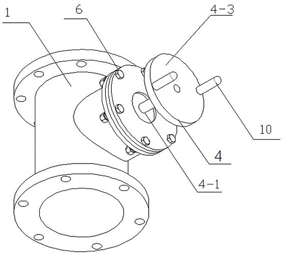
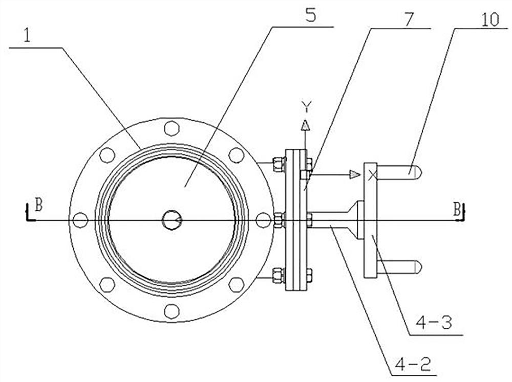
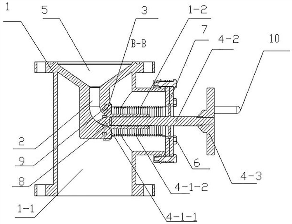
[0033] Such as Figure 1-3 As shown, a high-vacuum metal powder valve includes a valve body 1, an elbow 2, an abutment 3 and a valve core part 4, and a fluid channel 1-1 and a valve communicating with the fluid channel 1-1 are arranged in the valve body 1. The hollow cavity 1-2, the elbow 2 is installed in the fluid channel 1-1, the abutting piece 3 is connected with the end of the elbow 2 away from the inlet of the fluid channel 1-1, the valve core part 4 extends into the hollow cavity 1-2 and Contact with the abutment 3;

[0034] The spool part 4 includes a moving assembly 4-1, a valve stem 4-2 and a hand wheel 4-3. One end of the moving assembly 4-1 is adapted to the abutment 3, and one end of the valve stem 4-2 is connected to the moving assembly 4. -1 is threaded and its other end is connected with the handwheel 4-3, and the end of the valve stem 4-2 away from the thimble 4-1-1 is connected with the handwheel 4-3 through a quick-connect pin.

[0035] The valve stem 4-2 ...

Embodiment 2

[0045]Except the technical feature identical with embodiment 1, also comprise following difference:

[0046] When the valve stem 4-2 is located at 10mm, that is, the thimble 4-1-1 moves out of the center hole of the contact piece 3, the thimble 4-1-1 no longer blocks the elbow 2, and plays the role of opening the valve body, and the metal powder Outflow at maximum flow from fluid channel 1-1.

[0047] The invention works as follows:

[0048] The valve stem 4-2 is rotated by operating the handwheel 4-3 transmission device, and at the same time, the valve stem 4-2 drives the valve core part 4 through thread transmission to realize the opening and closing of the valve. -1-1 cooperate with each other, and the rotation of the handwheel 4-3 drives the valve stem 4-2 to move back and forth to control the flow of powder. The movement distance is 0~10mm. When the valve stem 4-2 reaches the position of 10mm, the valve It is in the fully open position in the pipeline. At this time, onl...


PUM


Abstract

The invention provides a high-vacuum metal powder valve. A fluid channel and a hollow cavity communicating with the fluid channel are formed in a valve body; a bent pipe is installed in the fluid channel; an abutting part is connected with one end, away from an inlet of the fluid channel, of the bent pipe; a valve element component extends into the hollow cavity and is in contact with the abutting part, and the valve element component comprises a moving assembly, a valve rod and a hand wheel; one end of the moving assembly is matched with the abutting part; one end of the valve rod is in threaded connection with the moving assembly, and the other end of the valve rod is connected with the hand wheel; an annular bump is arranged on the valve rod and fixedly installed on the valve body; and the moving assembly can move relative to the valve rod till the moving assembly abuts against the abutting part, so as to close the fluid channel. The high-vacuum metal powder valve has the beneficial effects that metal powder can smoothly pass through the valve, and the powder feeding amount can be controlled; the sealing effect of the valve body is good; the valve can withstand positive pressure; a design for preventing the metal powder from scouring the valve is arranged in the valve body, and erosive wear of the metal powder to sealing rings is effectively avoided; and the safety of the valve is greatly improved, and the service life of the valve is greatly prolonged.

Description

technical field [0001] The invention relates to the field of valves, in particular to a high-vacuum metal powder valve. Background technique [0002] With the rapid development of powder metallurgy, additive manufacturing, and aerospace industry, the production, storage, and transportation of metal powder require the powder to be isolated from the outside air throughout the process, and some core production processes require that the leakage rate of the powder container (tank) must reach the process level. Requirements, there should be no air leakage or powder leakage during transportation. The application fields of metal powder are becoming wider and wider, and the demand for powder is gradually increasing. In the production process of powder preparation, especially some powders that need to meet specific requirements, such as FGH4097 powder for aerospace discs, require extremely high sealing Environment, so during the process of powder preparation and subsequent screening...

Claims


Application Information

Patent Timeline
Patent Type & Authority Applications(China)
IPC IPC(8): F16K1/36F16K1/42F16K1/46F16K31/60F16K31/50F16L43/00
CPCF16K1/36F16K1/42F16K1/46F16K31/60F16K31/50F16L43/00
Inventor 王松杜少攀王庆相吴昊周洪宇党威望孙选朋李鑫梁书锦
Owner SINO EURO MATERIALS TECH OF XIAN CO LTD
Learn More